INSTALLATION MANUAL / USER MANUAL
REMOTE CONTROL PANEL RC102
PAGE: 5
JUL 18/2022
© 2022 Orolia S.A.S. All rights are strictly reserved.
• Stick the front plate (1a) onto the instrument panel;
• Install the LED mounting (2), with washer (2a) and nut (2b). Tighten
nut;
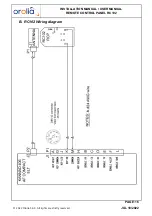
• Connect the anode (long leg) of LED (2c) to A of PCB (3a);
• Connect the cathode (short leg) of LED (2c) to C of PCB (3a);
• Connect wires to K and M of PCB (3a);
• Insert the LED into the LED stand (2d) taking care the flat part of the
LED be in front of the flat part of the LED stand;
• Insert LED (2c) fitted with LED stand (2d) inside the LED mounting (2);
• Install the switch and PCB assembly (3b+3a) with washers (3c) and
nuts (3d), locked position upwards. Tighten nut;
• Stuck the "identification label" (4) on the cable bundle near the PCB.
Front plate (1b)
• Place the front panel (1b) on to the instrument panel and use it as
drilling mask or;
• Trace the centers of the two holes according to drilling mask supplied;
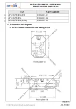
• Drill a hole Ø 8 mm for the LED mounting (2) (left of the panel);
• Drill a hole Ø6.5 mm for the switch (3b) (right of the panel);
Note: the switch (3b) is already soldered to a PCB (3a).
• Drill 4 holes of Ø 3 mm for the screws used to fix the RCP;
• Screw the front plate (1b) onto the instrument panel;
• Install the LED mounting (2), with washer (2a) and nut (2b). Tighten
nut;
• Connect the anode (long leg) of LED (2c) to A of PCB (3a);
• Connect the cathode (short leg) of LED (2c) to C of PCB (3a);
• Connect wires to K and M of PCB (3a);
• Insert the LED into the LED stand (2d) taking care the flat part of the
LED be in front of the flat part of the LED stand;
• Insert LED (2c) fitted with LED stand (2d) inside the LED mounting (2);
• Install the switch and PCB assembly (3b+3a) with washers (3c) and
nuts (3d), locked position upwards. Tighten nut;
• Stuck the "identification label" (4) on the cable bundle near the PCB.


