INSTALLATION MANUAL / USER MANUAL
REMOTE CONTROL PANEL RC102
PAGE: 4
JUL 18/2022
© 2022 Orolia S.A.S. All rights are strictly reserved.
4. RCP installation
A. Installation recommendations
IMPORTANT: Installation of this RCP is covered by Service Bulletin
"SB S1820513-25-02":
Refer to Section 1. Introduction, page 1
The RCP shall be installed in the cockpit. The RCP shall be readily
accessible from the pilot’s normal seated position.
CAUTION: RC102 RCP may only be installed with KANNAD 406 AF
COMPACT P/N S1840501-01 at amendment M or higher or on
KANNAD 406 AF COMPACT ER P/N S1840501-04. A WARNING label
is supplied with the kit and must be stuck on the 2-wire bundle on the
ELT side.
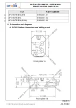
2 types of front plates may be installed. Choose the appropriate front plate
according to the aircraft’s instrument panel.
Connection of RC102 requires a 2-wire bundle. A pin-to-pin wiring has to
be provided by the installer with AWG24 wires. Shielded wires are
recommended.
The wires are soldered to a PCB installed on the switch. This operation can
be carried out before installation.
On the ELT side, the wires are soldered to a 12-pin plug that can be either
a standard "DIN12 connector" (P/N S1820514-03) or a connector with an
integrated serial memory module called "Programming Dongle"
(P/N S1820514-01).
B. RCP Installation procedure
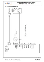
(1) Mount RCP
(
Refer to Figure 3: RCP mounting diagram
NOTE: Legs of LED must be protected by heat shrinkable sleeves.
Choose one of the front plates (1a or 1b) according to the space
available on the instrument panel.
Front plate (1a)
• Place the front plate (1a) on the instrument panel and use it as drilling
mask or;
• Trace the centers of the two holes according to drilling mask supplied;
• Drill a hole Ø 8 mm for the LED mounting (2) (top of the panel);
• Drill a hole Ø6.5 mm for the switch (3b) (bottom of the panel);
Note: the switch (3b) is already soldered to a PCB (3a)
• Tear off protection of front plate (1a) from self-adhesive film;


