STEP MOTOR-BASED MOTION CONTROL SYSTEM
C OtOt‘;00f1f).11(N-g6,,,
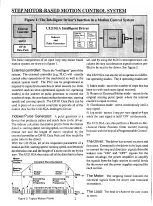
The basic components of an open loop step motor based
motion system are shown in figure 1.
External controller: This is the "intelligent" part of the
system. The external controller (e.g. PLC) will usually
control other operations of the machine(s) as well as the
motion system itself. T h e PLC can be programmed to
respond to inputs from switches or other sensors (i.e. limit
switches) and can send operational signals (i.e. operating
modes) to the indexer or pulse generator to control the
number of steps, the acceleration/deceleration rate, starting
speeds and running speeds. The DP-01 Data Pack can be
used in place of an external controller to provide all of the
motion data for the UI215GA Intelligent Driver.
Indexer/Pulse Generator: A pulse generator is a
device that produces pulses and sends them to the driver.
The indexer calculates the motion profile from the motion
data (i.e. starting speed, running speed, acceleration/decel-
eration rate and the length o f move) supplied by the
external controller or DP-01 Data Pack and then sends the
pulse train to the driver.
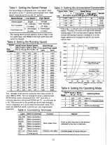
With the UI215GA, all of the important parameters of a
motion profile; starting speed, running speed, acceleration/
deceleration rate and the length of a move can be set by the
user. The UI215GA then takes all of the data that has been
M o t o r
A Velocity
Profile
C o n s t a n t R u n n i n g S p e e d
Starting
S p e e d
S l o p e =
A c c e l
T1 T 2
S l o p e = t
Decel
I n c r e a s i n g D e c r e a s i n g
P u l s e
P
u
l
s
e
F r e q u e n c y F r e q u e n c y
P u l s e
C
o
n
s
t
a
n
t
P u l s e F r e q u e n c y
TD1:9111).1 I I 11111111111111111111111111111111 I I T i m e
T 2
T
3
T
4
T3
T i m e
T 4
set, and by using the built in microprocessor, cal-
culates the step and direction signals (motion pro-
file) to be sent to the driver. See figure 2.
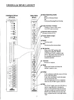
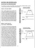
The UI215GA can also be set to operate in 4 differ-
ent operating modes. The 4 operating modes are:
1) Index mode - move the number of steps that has
been set with each start signal received.
2) Return to Electrical Home mode - return to the
original starting point (point where the internal
counter is equal to zero).
3) Continuous mode - move continuously until a
stop signal.
4) Jog mode - moves 1 step per start signal or 4 pps
while the start signal is held "ON" continuously.
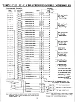
The UI215GA can also perform a Return-to-Me-
chanical Home Position (limit switch) hunting
function with the help of a Programmable Control-
ler.
T h e Driver: The driver has several sections and
functions. Contained in the driver is the logic used
to convert the step and direction signals from the
indexer into "ON" and "OFF" signals f o r the
motor windings, the power amplifier to amplify
the signals from the logic section to useful levels
for the motor and the power supplies required for
each section.
- T h e Motor: T h e stepping motor converts the
electrical signals from the driver into rotational
movements.
The Load: The load is whatever the user wants
to move.
Figure 2: Typical Motion Profile
2


