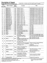
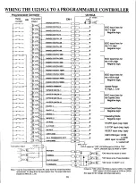

Description of Signals
Pin #
Name of Signal
Input/
Output
Function
Note
CN 1 CN 2
1
1
INDEX DATA 1
Input
Number of steps = 1
Selected when the photo coupler is "ON"
2
2
INDEX DATA 2
Input
Number of steps = 2
Selected when the photo coupler is "ON"
3
3
INDEX DATA 4
Input
Number of steps = 4
Selected when the photo coupler is "ON"
4
4
INDEX DATA 8
Input
Number of steps = 8
Selected when the photo coupler is "ON"
5
5
INDEX DATA 10
Input
Number of steps = 10
Selected when the photo coupler is "ON"
6
6
INDEX DATA 20
Input
Number of steps = 20
Selected when the photo coupler is "ON"
7
7
INDEX DATA 40
Input
Number of steps = 40
Selected when the photo coupler is "ON"
8
8
INDEX DATA 80
Input
Number of steps = 80
Selected when the photo coupler is "ON"
9
9
INDEX DATA 100
Input
Number of steps = 100
Selected when the photo coupler is "ON"
10
10
INDEX DATA 200
Input
Number of steps = 200
Selected when the photo coupler is "ON"
11
11
INDEX DATA 400
Input
Number of steps = 400
Selected when the photo coupler is "ON"
12
12
INDEX DATA 800
Input
Number of steps = 800
Selected when the photo coupler is "ON"
13
13
INDEX DATA 1000
Input
Number of steps = 1000
Selected when the photo coupler is "ON"
14
14
INDEX DATA 2000
Input
Number of steps = 2000
Selected when the photo coupler is "ON"
15
15
INDEX DATA 4000
Input
Number of steps = 4000
Selected when the photo coupler is "ON"
16
16
INDEX DATA 8000
Input
Number of steps = 8000
Selected when the photo coupler is "ON"
17
17
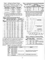
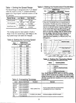
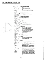
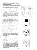
SPEED RANGE
Input
Select speed range High or Low
See Table 1
18
18
SPEED DATA 1
Input
Running Speed 1
See Table 2
19
19
SPEED DATA 2
Input
Running Speed 2
See Table 2
20
20
SPEED DATA 4
Input
Running Speed 4
See Table 2
21
21
SPEED DATA 8
Input Running Speed 8
See Table 2
22
22
RATE 1
Input
Acceleration/Deceleration Rate 1
See Table 3
23
23
RATE 2
Input
Acceleration/Deceleration Rate 2
See Table 3
24
24
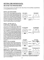
MODE 1
Input
Operating Mode 1
See Table 4
25
25
MODE 2
Input
Operation Mode 2
See Table 4
26
26
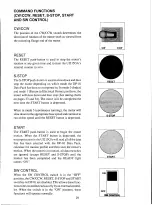
START
Input
Start Signal
Move starts on the leading edge of signal
27
27
SLOW DOWN/STOP
Input
Decelerate/Halt signal or
Decelerate to base speed
signal
Continuous Running Mode: Motor deceler-
ates to base speed; Index and Return Modes:
Motor decelerates and stops
28
28
RESET
Input
Emergency stop and counter reset
Motor stops with reset signal
29
29
CW/CCW DIRECTION
Input
CW rotation when the signal is
"OFF" and CCW rotation when
the signal is "ON"
30
30
ALL WINDINGS OFF
Input
Turns off the current to the motor
windings when the "ALL WINDINGS
OFF" signal is "ON"
Removes current for manual positioning
of motor, or to reduce motor
temperature
31
31
GND*
Common for all input lines
32
READY
Output
Signal is "ON" while the motor
is ready to be operated
33
MAGNETIC BRAKE
Output
Electromagnetic brake "ON"
and "OFF" signal
"ON" while the motor is running,
"OFF" for fail safe brake
34
TIMING
Output
"Phase V position signal output
"ON" when the motor is in the
"Phase W position
35
OVERHEAT ALARM
Output
Output signal is "ON" when
the temperature of the drivers
internal heat sink reaches
approximately 175°F (80°C)
Current to the motor is removed
unless the AHO switch is "OFF"
36
COM (EMITTER)*
Common for all output lines
An input signal is considered to be "ON" when there is continuity to ground (Pin #31).
An output signal is considered to be "ON" when it is LOW or CLOSED.
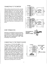
Connector CN1 and CN2 Input/Output Signals
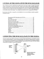
* Connect any external controller such as a programmable controller to CN1.
* * Connect the
Data Pack DP-01
(Available separately) to CN2.
Pin numbers I thru 31 on CN1 and CN2 are internally connected to
the
corresponding pins on either connector.
14
*There is no internal connection between pin
'31 (GND for inputs) and pin '36 (COM for
outputs).


