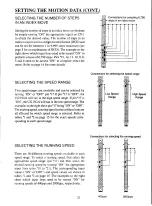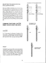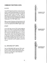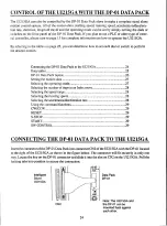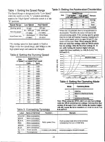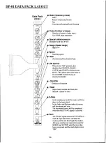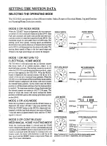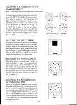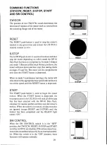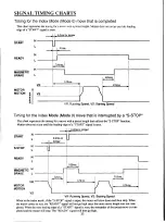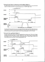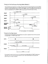
Timing for the Continuous Running Mode (Mode 3)
This chart represents the timing for a move that is continuously running (running until instructed to stop). Motion
will not occur until the leading edge of a "START" signal is seen. If a "S-STOP" signal is input, the motor will
decelerate to the base speed and continue running until a "RESET" signal is input and then stop. The motor will
come to an immediate stop if the "RESET" signal is input at anytime while the motor is running.
: 0.2ms or longer
START
S-STOP
RESET
READY
MAGNETIC
BRAKE
H
L
H
L
H
L
L
H
L
0.2ms
ms
VR
MOTION E I VS
MOTOR p
D
20ms
170ms
:At
!=. 70ms
VR: Running Speed, VS: Starting Speed
Timing for the Data Inputs
This chart represents the timing required for data inputs to be properly recognized. Motion will not occur until
the leading edge of a "START" signal is seen.
DATA
START
READY
L
H
X
L 0.2ms or longer
▶
H
L
10.2MS
1 ms or longer
.11ms
Do not change the input data until at least lms has passed after the leading edge of a "START" signal is seen.
Input lines 1 thru 25 are used as the data input lines. Lines 1 thru 25 are the same on connectors CN1
and CN2 and are internally connected.
35

