Connection
31
▐
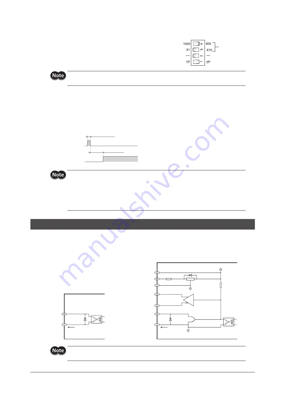
×10 (Resolution selection) input
Selects and switches to 10 times either of the resolution that has been
selected with the resolution select switches.
Turning the ×10 input to “ON” will select and switch to “×10 resolution.”
Turning the ×10 input to “OFF” will select and switch to “×1 resolution.”
Refer to p.35 for the resolution select switches.
Resolution select
switches
Be sure to set the resolution select switch to “×1” when ×10 input is used. If the switch is set to “×10,”
the resolution will remain at 10 times, regardless of the ×10 input.
ACL (Alarm clear) input
The input clears the ALARM output issued when a protective function has been triggered.
The ALARM output remains “ON” when the driver is operating normally, then turns “OFF” when a protective function is
triggered. For details, refer to “ALARM output” on p.32 and “8 Protective functions” on p.37.
Setting the ACL input in the ON state clears the ALARM output. To cancel the ALARM output, be sure to remove the
cause of the problem that has triggered the protective function before turning the power back on.
ACL input
ALARM output
ON
OFF
ON
OFF
0.5 s or less
0.1 s or more
•
Turning the power back on will clear the ALARM output. To cancel the ALARM output, be sure to
remove the cause of the problem that has triggered the protective function before turning the
power back on. After the power has been shut off, wait at least 10 seconds before turning the
power back on.
•
The overcurrent protection, EEPROM data error and system error cannot be cleared using the ACL
input. Clear these errors by cycling the power. If the problem persists, please contact the nearest
Oriental Motor office.
6-8
Output signals
Driver output signals are photocoupler/open-collector output, transistor open-collector output for the TIM.1, ASG1
and BSG1 outputs, and line-driver output for the TIM.2, ASG2 and BSG2 outputs.
The signal state represents the “ON: Carrying current” or “OFF: Not carrying current” state of the internal photocoupler
rather than the voltage level of the signal.
TIM.1, TIM.2, ASG1, ASG2, BSG1, BSG2
+5 V
0 V
26C31 or equivalent
1
3
2
17, 19, 27
Line-driver output
18, 20, 28
13, 15, 23
Open-collector output
14, 16, 24
30 VDC
15 mA or less
30 VDC
15 mA or less
ALARM, END
25, 29
26, 30
Driver internal circuit
Driver internal circuit
0 V
Be sure to use the same voltage for C.OFF, ×10 and ACL inputs and TIM.1/TIM.2, ASG1/ASG2 and
BSG1/BSG2 outputs.


