9
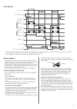
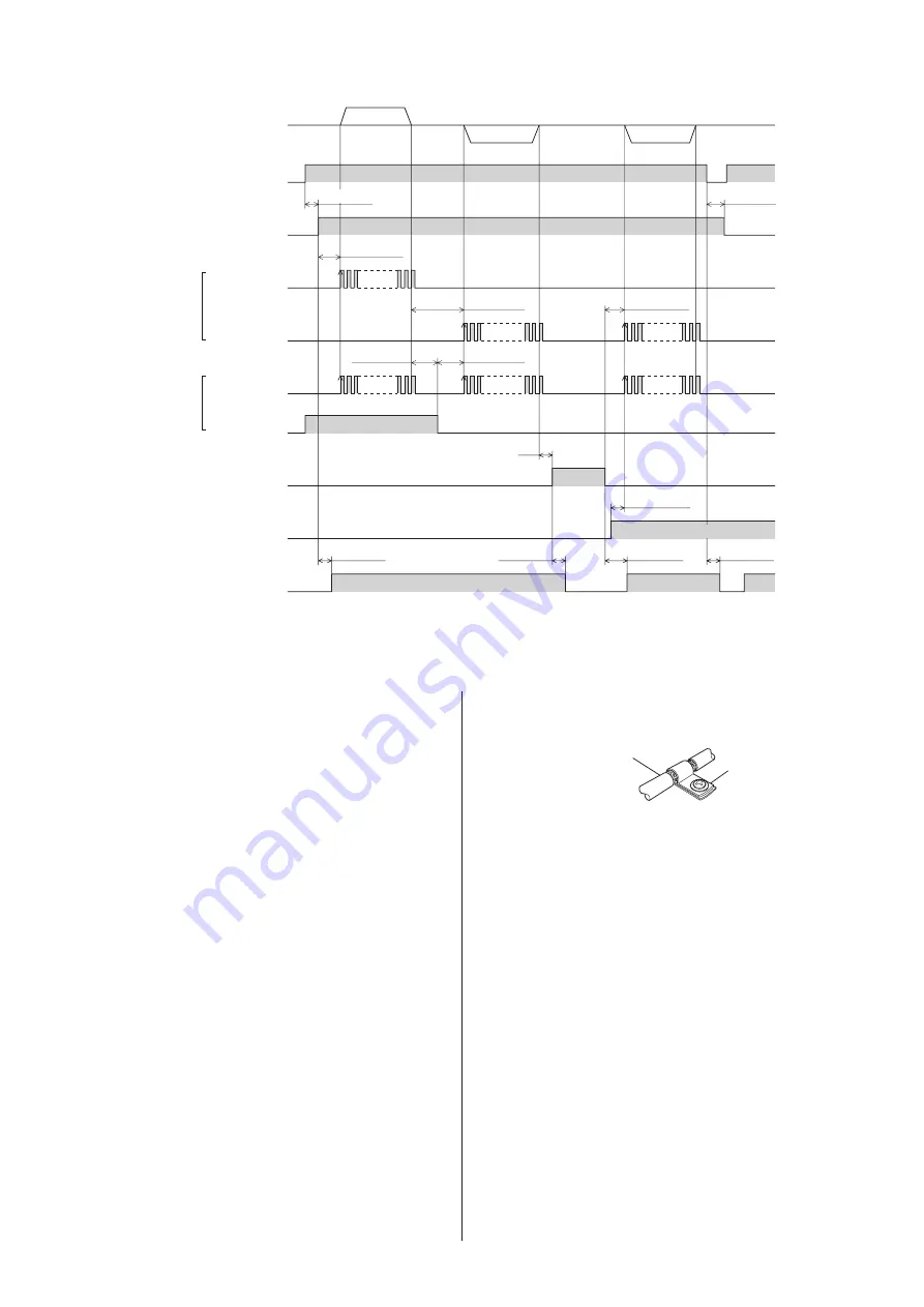
Timing chart
*3
ON
OFF
ON
OFF
ON
OFF
ON
OFF
ON
OFF
ON
OFF
ON
OFF
CW input
DIR input
CCW input
PLS input
AWO input
Motor operation
Power supply input
ON
OFF
ALM output
Excitation
Non-excitation
Motor excitation
5 µs or more
*1
0.1 s or more
0.1 s or less
0.2 s or less
0.2 s or less
0.2 s or less
0.2 s or less
10 s or less
5 µs or more
5 µs or more
*2
CS input
Base step angle
Step angle set by the driver switch
2-pulse input
mode
1-pulse input
mode
5 ms or more
*1
*1
CW
CCW
CCW
0.2 s or more
*1 The interval for switching the motor direction represents the response time of the circuit. Set this interval to an appropriate time after which the motor will respond.
*2 It varies depending on the moment of load inertia, load torque, starting frequency, and so on.
*3 When cycling the power, turn off the power and wait for the PWR/ALM LED to turn off.
Noise measures
The electrical noise is of two types: One is a noise to invade into the driver
from the outside and cause the driver malfunction, and the other is a noise to
emit from the driver and cause peripheral equipments malfunction.
For the noise that is invaded from the outside, take measures to prevent the
driver malfunction. It is needed to take adequate measures because signal
lines are very likely to be affected by the noise.
For the noise that is emitted from the driver, take measures to suppress it.
z
Measures against electrical noise
There are the following three methods mainly to take measures against the
electrical noise.
•
Noise suppression
y
When relays or electromagnetic switches are used together with the
system, use noise filters and CR circuits to suppress surges generated by
them.
y
Cover the driver by a metal plate such as aluminum. This is effective in
shielding the electrical noise emitted from the driver.
•
Prevention of noise propagation
y
Place the power lines, such as the motor and power supply cables, keeping
a distance of 100 mm (3.94 in.) or more from the signal lines, and also do
not bundle them or wire them in parallel. If the power cables and signal
cables have to cross, cross them at a right angle.
y
Use shielded twisted pair cables of AWG22 (0.3 mm
2
) for power lines and
AWG24 to 22 (0.2 to 0.3 mm
2
) for signal lines.
y
Keep cables as short as possible without coiling and bundling extra lengths.
y
To ground a shielded cable, use a metal cable clamp that will maintain
contact with the entire circumference of the cable. Ground the cable clamp
near the product.
Cable clamp
Shielded cable
y
When grounding PE terminals of multiple drivers to a grounding point,
it becomes more effective to block the electrical noise since impedance
on the grounding point is decreased. However, ground them so that a
potential difference does not occur among the grounding points. An
accessory connection cable (for signal) that includes a ground wire is
provided. Refer to p.12 for details.
•
Suppression of effect by noise propagation
y
Loop the noise propagated cable around a ferrite core. Doing so will
prevent the propagated noise invades into the driver or emits from the
driver. The frequency band in which an effect by the ferrite core can be
seen is generally 1 MHz or more. Check the frequency characteristics of the
ferrite core used. To increase the effect of noise attenuation by the ferrite
core, loop the cable a lot.
y
Use the line driver type, which is less likely to be affected by electrical noise,
for the output circuit of pulse signals. If the pulse signal of the controller is
of the open collector type, use an accessory pulse signal converter for noise
immunity. Refer to p.12 for details.

