5
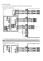
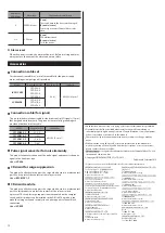
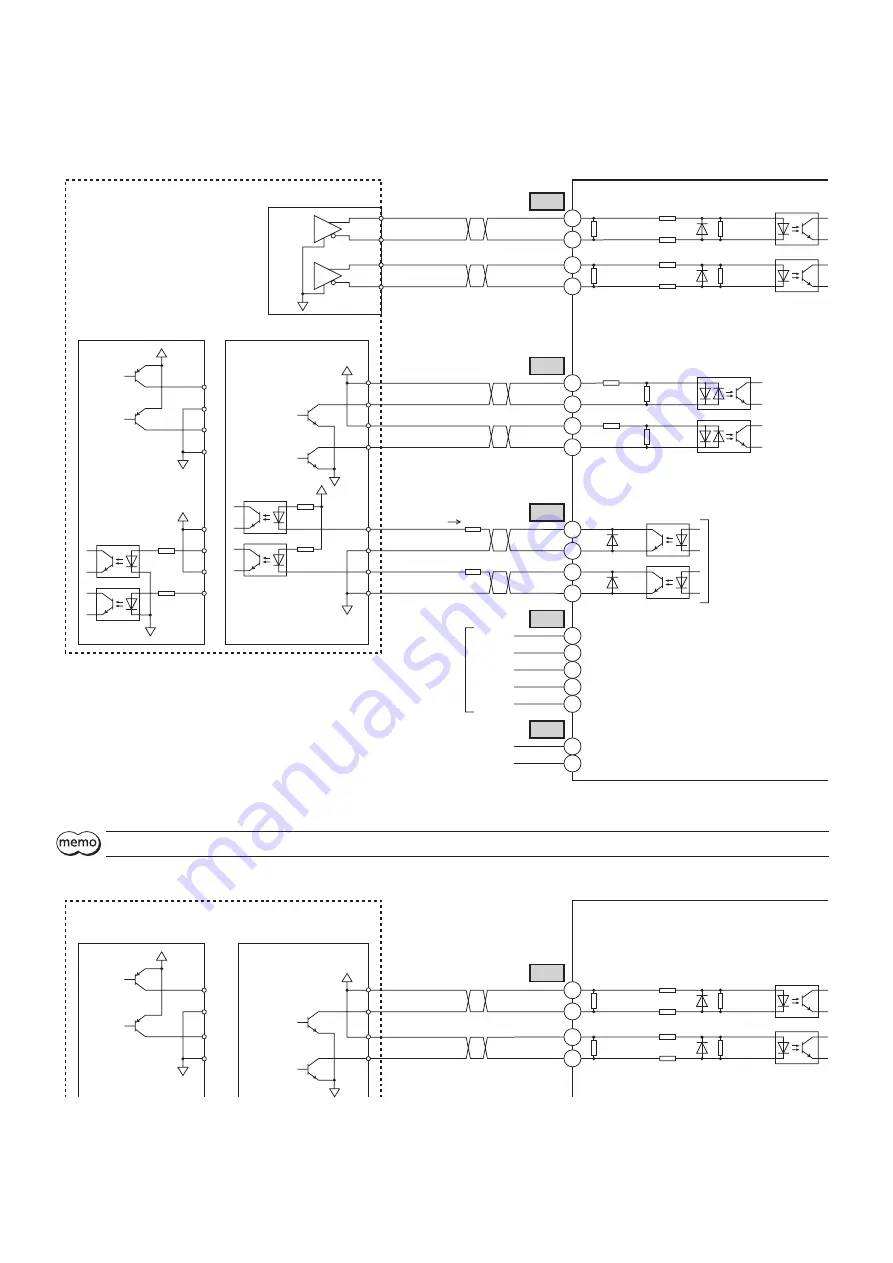
Connection example
z
When using the voltage of input signals at 5 VDC (Refer to p.6 for when connecting 24 VDC.)
•
When pulse input is of line driver type
Driver
R0
0 V
0 V
0 V
0 V
GND
24 VDC±10%
PLS (CW)
DIR (CCW)
AWO
ALM
CN3
CN3
CN3
CN1
Red
Blue
Motor lead wire
*1
Twisted pair cable
Green
Black
5
4
3
2
1
4
3
2
1
10
9
R0
TIM
12
11
6
5
-
+
Orange*2
CN2
100 Ω
Current sink output circuit
Current source output circuit
Controller
100 Ω
100 Ω
100 Ω
470 Ω
2.2 kΩ
2.2 kΩ
2.2 kΩ
2.2 kΩ
1 kΩ
CS
8
7
470 Ω
1 kΩ
0 V
30 VDC or less
30 VDC or less
Output saturated voltage
0.5 V max.
5 VDC
5 VDC
*2
10 mA or less
*1 Connector pin assignments vary depending on the motor. For details, refer to "Connecting the motor" on p.4.
*2 This orange lead wire is for 5-phase stepping motor. For 2-phase stepping motor, do not connect anything to the pin No.3 since there is no orange lead wire.
Use output signals at 30 VDC, 10 mA or less. If the current exceeds 10 mA, connect an external resistor R0 so that the current becomes 10 mA or less.
•
When pulse input is of open-collector type
Driver
0 V
0 V
PLS (CW)
CN3
2
1
100 Ω
Current sink output circuit
Twisted pair cable
Current source output circuit
Controller
100 Ω
100 Ω
100 Ω
2.2 kΩ
2.2 kΩ
2.2 kΩ
2.2 kΩ
DIR (CCW)
4
3
5 VDC
5 VDC

