


7
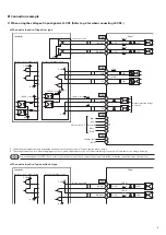
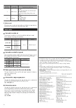
Connector pin assignment
1 2 3
• • • • • •
CN3
12
11
10
1 2
+ -
3 4 5
CN2
CN1
z
CN1 (power supply)
Pin No.
Direction
Signal name
Description
+
IN
POWER
+24 VDC
−
GND
z
CN2 (motor)
Pin No.
Direction
Signal name
Description
1
OUT
MOTOR
Blue motor lead wire
2
Red motor lead wire
3
Orange motor lead wire *
4
Green motor lead wire
5
Black motor lead wire
* This orange lead wire is for 5-phase stepping motor. For 2-phase stepping motor,
do not connect anything to the pin No.3 since there is no orange lead wire.
Connector pin assignments vary depending on the motor. For details,
refer to "Connecting the motor" on p.4.
z
CN3 (I/O signals)
Pin No.
Direction
Signal name
Description
1
IN
PLS (CW)
+
Pulse (CW pulse) input *
2
−
3
DIR (CCW)
+
Rotation direction (CCW
pulse) input *
4
−
5
AWO
+
All windings off input
6
−
7
CS
+
Step angle switching input
8
−
9
OUT
ALM
+
Alarm output
10
−
11
TIM
+
Timing output
12
−
* These inputs serve as the pulse input (PLS) and rotation direction input (DIR) in
the 1-pulse input mode, or CW pulse input (CW) and CCW pulse input (CCW) in
the 2-pulse input mode.
Applicable connector
Type
Application
Model
Connector housing
For power supply (CN1)
51103-0200 (Molex)
For motor (CN2)
51103-0500 (Molex)
For I/O signals (CN3)
51103-1200 (Molex)
Contact
−
50351-8100 (Molex)
Applicable crimping tool
−
63811-8100 (Molex)
Type
Application
Applicable lead wire
y
For power supply (CN1)
AWG22 (0.3 mm
2
)
Outer sheath diameter:
ø1.15 to 1.8 mm (ø0.045 to 0.071 in.)
Strip length of the insulation cover:
2.3 to 2.8 mm (0.091 to 0.11 in.)
y
For motor (CN2), for I/O signals (CN3)
AWG24 to AWG22 (0.2 to 0.3 mm
2
) *
Outer sheath diameter:
ø1.15 to 1.8 mm (ø0.045 to 0.071 in.)
Strip length of the insulation cover:
2.3 to 2.8 mm (0.091 to 0.11 in.)
* About the connector for motor (CN2) of the
CVD228
and
CVD524
, use lead wires of AWG22
(0.3 mm
2
).
y
For the I/O signals cable, use a twisted pair cable.
y
Keep the wiring distance as short as possible [less than 2 m (6.6 ft.)] to
suppress the effect of noise.
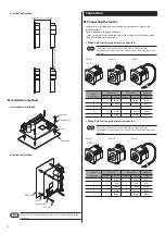
For the motor of the frame size 20 mm (0.79 in.) [
PKP213
type], since
the wire diameter of the motor cable is AWG26 (0.14 mm
2
), it is too
thin to fit in the supplied connector for motor. Provide the cable of
AWG24 to AWG22 (0.2 to 0.3 mm
2
) yourself, and connect by using it.
Cable of AWG24 to AWG22
PKP213
Driver
Connecting the power supply
Use a power supply that can supply the following current capacity.
When the power is turned on, the PWR/ALM LED will be lit in green.
Driver model
Input power supply
voltage
Power supply
current capacity
CVD205
+24 VDC±10%
0.5 A or more
CVD215
1.3 A or more
CVD223
2.0 A or more
CVD228
3.0 A or more
CVD512
1.7 A or more
CVD518
2.8 A or more
CVD524
2.7 A or more
y
When connecting, pay attention to the polarity of the power supply.
Reverse-polarity connection may cause damage to the driver.
y
Have the connector plugged in securely. Insecure connection may
cause malfunction or damage to the driver.
y
When unplugging the connector, do so while spreading the latches
on the connector a little.
y
When cycling the power or plugging/unplugging the connector,
turn off the power and wait for the PWR/ALM LED to turn off.
y
Separate I/O signals cable at least 100 mm (3.94 in.) from
electromagnetic relays and other than inductance loads.
Additionally, route I/O signals cable perpendicular to power supply
cable and motor cable, rather than in a parallel fashion.
y
Do not route the power supply cable in the same conduits as other
power supply lines and motor cable.
y
If the motor cable or power supply cable generates an undesirable
amount of noise depending on the wiring or configuration, shield
the cable or install a ferrite core.