4 Installation
-
13
-
4.3 Load installation
When installing the load to the motor or gearhead, ensure that the motor output shaft
or gearhead output shaft and load shaft are aligned with each other. Optional flexible
couplings are available (sold separately).
The output shaft of the round shaft type and geared type is provided with a flat. Use
double point screws on the flat and provide reliable locking to prevent idle rotation
of the load.
The combination type gearhead output shaft is provided with a key groove. A key
groove must also be provided on the side of the load to be installed. Use the attached
key to lock it in position.
Unit model
Key dimensions
AXH230KC-
4 mm (0.1575 in.)
AXH450KC-
5 mm (0.1969 in.)
AXH5100KC-
6 mm (0.2362 in.)
Note
•
When connecting the motor (gearhead) with a load, care must be taken to
ensure adequate alignment, belt tension and pulley parallelism. The
coupling and pulley locking screws must be clamped firmly in position.
•
To install a coupling or pulley to the motor output shaft or gear output shaft,
sufficient care must be taken not to damage the output shaft and bearing.
•
Do not modify or machine the motor (gearhead) output shaft. It may damage
the bearing, which may result in motor (gearhead) failure
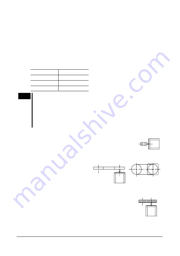
Direct connection of coupling
Ensure that the motor (gearhead) output shaft and load shaft are
aligned with each other.
Belt connection
Ensure that the centerlines of the
motor (gearhead) output shaft and load
shaft are parallel with each other, and
that the line connecting the centers of
both pulleys and shaft are at a right
angle to each other.
Gear connection
Provide correct engagement with the center of the gear tooth
surface to ensure that the motor (gearhead) output shaft and gear
shaft are parallel to each other.


