background image

6


7


Section 2: 

Installation

Required Tools

• Phillips Screwdriver
• Wire Strippers

1. Select a Location 
When choosing a location for your timer, consider the 
following:

•  Choose a location near an electrical outlet .
•  ensure operating temperatures are not below 32° or 

above 158° Fahrenheit (below 0° Celsius or above 70° 
Celsius) .

•  locate the timer where there is easy access to sprinkler 

wire (from valves) .

2. Mount the Timer

•    Use the mounting template (included) to mark the 

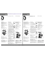
mounting screw location on the wall . See figure 1

•  Install a No . 8 screw into wall in the upper template 

location . leave the screw head protruding 1/8” (3mm) 
from wall . Use expanding anchors (included) in plaster 
or masonry, if necessary, for a secure hold .

•  slip the timer over protruding screw (using keyhole slot 

in back of timer) . See figure 2

•  Drive a No . 8 screw through one of the two pre-formed 

holes located in lower corners of the cabinet . See figure 2

3. Connecting the Timer to Valves
Wiring Electric Valves 
Taking the sprinkler wire, strip 1/2” (12 mm) of the 
plastic insulation off the end of each individual wire .  
Connect one wire from each valve (it doesn’t matter 
which wire) to the “Common” sprinkler wire (usually 
white in color) . Next connect the remaining wire from 
each valve to a separate colored sprinkler wire .  

See figure 3

Note: The maximum loading for each station/pump is 250mA 

(one valve), the maximum loading for the timer is 500mA.

Figure 2: Hang timer on screw using keyhole

Keyhole

Pre-formed

mounting holes

No. 8 Screw

Wall

1/8"

Figure 1: Use Mounting Template (included)

Figure 3:

Wiring Electric Valves

If the distance between the sprinkler timer and valves is 

under 700’ (210 m), use Orbit

®

 sprinkler wire or 20 gauge 

(AWG) plastic jacketed thermostat wire to connect the 

sprinkler timer to the valves. If the distance is over 700’ (210 

m), use 16 gauge (AWG) wire.

Important:

 The wire can be buried in the ground; however, 

for more protection wires can be pulled through PVC pipe 

and buried underground. Be careful to avoid burying the 

wires in locations where they could be damaged by digging 

or trenching in the future.
All wires should be joined together using wire nuts, solder, 

and/or vinyl tape. In wet environments like a valve box it 

is recommended to use Orbit Grease Caps or Speed Seals 

to prevent corrosion of the connection and for protection 

from water infiltration.

Connecting Sprinkler Wires to the Timer 
Taking the sprinkler wire, strip 1/4” (6 mm) of the 
plastic insulation off the end of each individual wire .  
Connect  the “Common” sprinkler wire (usually white in 
color) to the terminal labeled “CoM” .  Next connect the 
remaining wires to a separate terminal  . See Figure 4 
To avoid electrical hazards and damage to the timer, 
only one valve should be connected to each station .  See 

Figure 4

solenoid

Wire Nut

To Timer

Valve

Common 
Wire

Содержание 28954

Страница 1: ...additional instructions Translation Approval Code LB682594 color non printing PMS PMS color non printing PMS Registration K Printers are responsible for meeting print production requirements Any chan...

Страница 2: ...Set Logic simple programming and setup are combined with the latest timer technology and versatility Your new timer provides convenience and flexibility letting you run a fully automatic a semi autom...

Страница 3: ...RROW To go back to the previous setting watering station or move to other programs settings RAIN DELAY To pause operation for 24 72 hours due to rain or other factors To increase a numeric setting To...

Страница 4: ...imum loading for each station pump is 250mA one valve the maximum loading for the timer is 500mA Figure 2 Hang timer on screw using keyhole Keyhole Pre formed mounting holes No 8 Screw Wall 1 8 Figure...

Страница 5: ...commended Remove the plastic strip to activate the pre installed battery See page 12 for battery replacement Note The battery alone will not operate the valves in your sprinkler system The sprinkler t...

Страница 6: ...day an interval of 3 will water every 3rd day etc Odd or Even Days Use the buttons to move to the ODD or EVEN day watering Press or ENTER On this screen the RUN TIME or duration for each station is se...

Страница 7: ...ual Watering press CLEAR The timer will go back to your original automatic watering schedule Example To manually water on station 3 for five minutes press the MANUAL button then press the buttons unti...

Страница 8: ...ed After the first program finishes the next program will begin Rain Delay A feature that postpones the running of a scheduled watering program for a specific duration Solenoid The electrical part on...

Страница 9: ...sponsible for consequential or incidental cost or damage caused by the product failure Orbit liability under this warranty is limited solely to the replacement or repair of defective parts To exercise...

Страница 10: ...nnect the equipment into an outlet on a circuit different from that to which the receiver is connected Consult the dealer or an experienced radio TV technician for help Caution This appliance is not i...

Страница 11: ...riego previa o moverse a otros programas configuraciones RAIN DELAY Para pausar el funcionamiento durante 24 a 72 horas debido a lluvias u otros factores Para aumentar una configuraci n num rica Para...

Страница 12: ...n forma de bocallave con un tornillo Figura 1 Utilice la plantilla de montaje incluida Figura 3 Cableado de las v lvulas el ctricas Nota La carga m xima para cada estaci n bomba es 250 mA una v lvula...

Страница 13: ...or Enchufe el transformador en un tomacorriente el ctrico de 110 V Consulte la figura 5 5 Active la bater a Se requiere una bater a de litio CR2032 incluida para mantener el programa en la memoria dur...

Страница 14: ...n parpadear para indicar la selecci n La pantalla mostrar la letra del programa A o B Presione los botones para pasar de un d a a otro a trav s de las opciones Presione o ENTER para seleccionar un d...

Страница 15: ...usando los TIEMPOS DE FUNCIONAMIENTO programados Si no se han configurado TIEMPOS DE FUNCIONAMIENTO no suceder nada y la pantalla volver a la hora del d a Conexi n de un detector de lluvia Conecte el...

Страница 16: ...era estaci n programada V LVULA Suministra agua a una estaci n o rea espec ficos La abertura y el cierre de la v lvula se realizan con la corriente el ctrica que suministra el temporizador de regador...

Страница 17: ...ispositivo cumple con la Secci n 15 de las reglas de la FCC El funcionamiento est sujeto a las siguientes dos condiciones 1 Este dispositivo no debe causar interferencia perjudicial y 2 deber aceptar...

Отзывы: