8
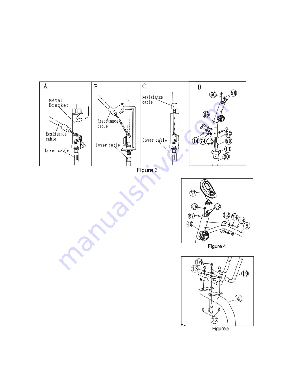
control will be extended to the longest), then put the end of resistance cable into the spring hook of Tension
control wire (50) as shown on drawing
A
of figure 3. Pull the resistance cable up and force it into the gap of
metal bracket of Tension control wire (50) as shown on drawing
B
of figure3. Connect the resistance cable
with the Tension control wire (50) completed as shown on drawing
C
of figure 3. If the upper side of the
tension control wire cannot fix perfectly in the gap of metal bracket, please adjust the nut which below the
bracket to the suitable position.
c. Install the Front upright tube (46) to the Main frame (30) with four sets of M8×20 Bolt (14),
φ
8 spring
washer (74),
φ
8 Arc washer (12).
4) Install the Computer
a. Connect the Sensor wire (56) and the hand pulse wire I (58) to the
wires that come from the Computer (57), put the extra wires into the
hole of the Front upright tube (46). Attach the Computer (57) to the top
of Front upright tube (46) perfectly and tighten with Crosshead bolt
M5*10 (67). (See figure 4)
b. Attach the Front small handlebar tube (8) to the Front upright tube
(46) with two sets of M8×20 Bolt (14)
,φ
8 spring washer
(
74
)
and
φ
8 Arc washer (12).
5) Install the Seat cushion frame
Attach the Seat cushion frame (19) to the Seat cushion adjustor (4) with
four sets of M8*16 bolts (22) ,
φ
8 flat washer (13) and Nylon nut M8
(16). (See figure 5)
6) Install and adjustment of seat cushion and back cushion
Install the seat cushion (17) and back cushion (18)to seat cushion frame
(19) with 8 sets of M8*40 bolts (15),
φ
8 Flat washers (13). (See
Figure 6 a, 6b)


