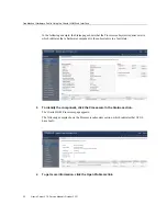

Troubleshoot Hardware Faults Using the Oracle ILOM Web Interface
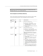
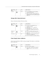
There are two status indicators (LEDs) on each port. These indicators are visible from the rear
of the server.
Status Indicator
Name
Location
Color
State and Meaning
RJ-45 10GbE Ports
Activity
Top left
Green
■ ON – Link up.
■ OFF– No activity.
■ FLASHING – Packet activity.
Link speed
Top right
Bi-colored:
Amber/Green
■ OFF – 100BASE-T link (if link up).
■ Green ON – 1000BBASE-T link.
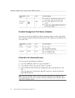
SFP+ 10/25GbE Ports
Activity
Top
Green
■ OFF– No activity.
■ FLASHING – Packet activity.
Link Speed
Bottom
Bi-colored:
Amber/Green
■ OFF – No activity.
■ Amber ON – 10GbE link.
■ Green ON – 25GbE link.
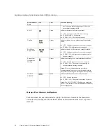
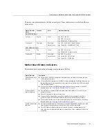
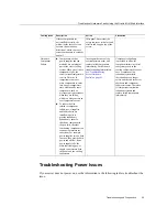
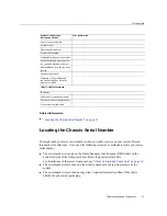
Motherboard Status Indicators
The motherboard contains the following status indicators (LEDs).
Status Indicator
Description
DIMM Fault Status
Indicators
■ Each of the 24 DIMM sockets on the motherboard has an amber fault status indicator
(LED) associated with it.
■ If Oracle ILOM determines that a DIMM is faulty, pressing the Fault Remind button on
the motherboard I/O card signals the service processor to light the fault LED associated
with the failed DIMM.
■ For more information on DIMM fault status indicators and the location of the Fault
Remind button, see
“Servicing the DIMMs (CRU)” on page 97
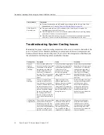
Processor Fault
Status Indicators
■ The motherboard includes a fault status indicator (LED) adjacent to each of the two
processor sockets.
■ These LEDs indicate when a processor fails.
■ Pressing the Fault Remind button on the motherboard I/O card signals the service
processor to light the fault status indicators associated with the failed processors.
■ For more information on processor fault status indicators and the location of the Fault
Remind button, see
“Servicing Processors (FRU)” on page 137
Fault Remind Status
Indicator
■ This status indicator (LED) is located next to the Fault Remind button and is powered
from the super capacitor that powers the fault LEDs on the motherboard.
■ This LED lights to indicate that the fault remind circuitry is working properly in
cases where no components failed and, as a result, none of the component fault LEDs
illuminate.
Troubleshooting and Diagnostics
33
Содержание X7-2
Страница 1: ...Oracle Server X7 2 Service Manual Part No E72445 03 October 2017 ...
Страница 2: ......
Страница 14: ...14 Oracle Server X7 2 Service Manual October 2017 ...
Страница 86: ...86 Oracle Server X7 2 Service Manual October 2017 ...
Страница 92: ...Install a Power Supply Remove a Power Supply on page 88 92 Oracle Server X7 2 Service Manual October 2017 ...
Страница 96: ...96 Oracle Server X7 2 Service Manual October 2017 ...
Страница 110: ...110 Oracle Server X7 2 Service Manual October 2017 ...
Страница 136: ...136 Oracle Server X7 2 Service Manual October 2017 ...
Страница 150: ...150 Oracle Server X7 2 Service Manual October 2017 ...
Страница 162: ...162 Oracle Server X7 2 Service Manual October 2017 ...
Страница 168: ...168 Oracle Server X7 2 Service Manual October 2017 ...
Страница 178: ...178 Oracle Server X7 2 Service Manual October 2017 ...
Страница 184: ...184 Oracle Server X7 2 Service Manual October 2017 ...
Страница 192: ...192 Oracle Server X7 2 Service Manual October 2017 ...
Страница 216: ...216 Oracle Server X7 2 Service Manual October 2017 ...
Страница 252: ...252 Oracle Server X7 2 Service Manual October 2017 ...
Страница 282: ...282 Oracle Server X7 2 Service Manual October 2017 ...
Страница 306: ...306 Oracle Server X7 2 Service Manual October 2017 ...


