


OPTIMUM
M A S C H I N E N - G E R M A N Y
Version 1.0.1 2014-05-16
Page 114
Original operating instructions
TU2506 | TU2506V | TU2807 | TU2807V
GB
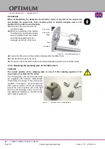
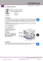
ATTENTION!
When disassembling the workpiece chuck (lathe chuck), it may fall on the engine bed
and damage the guide rails. Put a wooden plank or another adequate part on the
machine bed in order to avoid damage.
Disconnect the machine from the
electrical supply.
Block the revolutions of the spindle
for instance by inserting the square
seat of the lathe chuck. Also make
sure that the engine bed is not
damaged by the arm of the lever.
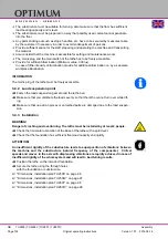
Img.3-10:
Dismantling lathe chuck
Loosen the three nuts on the spindle to disassemble the lathe chuck.
Take the lathe chuck to the front.
If required, loosen the lathe chuck by knocking slight with a plastic tip or a rubber mallet.
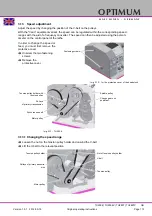
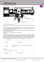
3.12.1 Replacing the clamping jaws on the lathe chuck
CAUTION!
The correct position of the clamping jaws is correct if after twisting together of the
chuck jaws are centered at the center.
The clamping jaws and the three-jaw chuck
are equipped with numbers. Nevertheless
check before the change, if the numbers are
readable - if necessary - check the jaws and
their original position. Insert the clamping
jaws at the correct position and in the right
order into the three-jaw chuck. Do not con-
fuse additional markings on the lathe chuck
with number sequences.
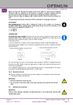
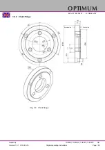
Img.3-11:
Three-jaw chuck / clamping jaws
Lathe chuck
Lathe chuck
flange
Nuts
Short taper
1
2
3
3
2
1


