


OPTIMUM
M A S C H I N E N - G E R M A N Y
Assembly
Version 1.0.1 2014-05-16
Page 110
Original operating instructions
TU2506 | TU2506V | TU2807 | TU2807V
GB
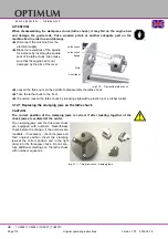
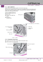
3.8.3 Mounting instruction of collet chuck holder
Mounting of collet chuck holder 344 1305 on your lathe.
Proceed as follows.
Mark out the position of the jaw chuck
at the spindle flange before disman-
tling with an e.g. felt-tipped pen. This
allows an identical reassembly.
Dismantle the jaw chuck.
Clean all faces of the spindle nose and
of the collet chuck holder extremely
thoroughly.
Dismantle the thread pins of the jaw
chuck and screw in the thread pins into
the collet chuck holder.
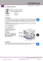
Measure the run out of the spindle
flange. Mark out the greatest positive
rash of the dial gauge at the spindle
flange with an e.g. felt-tipped pen.
Attach the collet chuck holder to the
spindle flange, tighten the nuts easily.
Pull in the nuts stepwise ones and uni-
formly alternating at least three times
in succession (you receive the run out
possible for best only this way).
Measure the run out of the collet chuck
holder at the conical surface.
Position the collet chuck holder by
turning each 120° at the spindle flange
to the highest run out precision is
achieved.
Mark out the position of the highest cir-
cularity accuracy of spindle flange with
collet chuck holder and assemble after
this the collet chuck holder on the
highest circularity accuracy position.
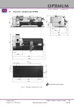
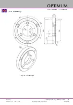
Img.3-5:
Collet chuck holder 344 1305 without union
nut.
Spindle flange
(short-taper seat)
Measuring position
Set screw
Measuring
position


