4
Owner’s guide
Rev. 1.3
2.
Controls and connectors
1.
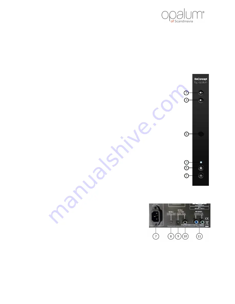
Status indicator
Indicates the current status using different colors and flash modes. For
details see section 3.
2.
Standby
Use this button to turn on the system or to put it into standby. This
button is also used to enter certain “Programming modes”.
3.
Volume up
This button can be used to increase the volume offset up.
4.
Volume down
This button can be used to decrease the volume offset down.
5.
Bluetooth pairing
Use this button to start the Bluetooth pairing process, which link your
Bluetooth enabled device to the system. This ensures that only devices
linked to the system will actually be able to use the system.
6.
IR sensor window
The IR sensor is placed behind this window.
7.
Power socket
Mains power connection. Make sure connector is firmly attached.
8.
Analog input
Connection for any analog source, like for instance TV (headphone or
analog out), MP3 players and similar devices.
9.
Digital input, coaxial*
Connection for digital S/PDIF equipment (e.g. computer, CD, DVD
TM
,
Blu-ray
TM
, flat screen TV, etc.) using coaxial cabling. (These are
trademarks of their respective owners).
10.
Digital inputs, optical*
Connection for digital S/PDIF equipment (e.g. computer, CD, DVD
TM
,
Blu-ray
TM
, flat screen TV, etc.) using optical fiber (TOSLINK
TM
). (These
are trademarks of their respective owners).
11.
Speaker link
Connect the supplied speaker link cable to this connector to connect the
two speaker boxes.
Front panel:
Rear panel:
* NOTE:
Use uncompressed stereo PCM audio data only. Data rates of 44.1, 48, 88.2 and 96 kHz are supported in 16 and 24 bits. Both 176.4
and 192 kHz in 16 and 24 bit are also supported using digital coax input. If connecting a multi-channel source (such as a TV, DVD
player, computer, etc.) setup this source to output uncompressed two channel (stereo) PCM data.


