


Installation Instructions EC 2-25 Lift
(Subject to technical alterations! - Status 09/2018)
This is a translation. The German original shall prevail.
Page 9 of 50
Note:
The gear unit is sealed oil-tight for transportation. With the screw plug or cap in place, the
gear cannot vent air. Starting operation with the screw plug still in place can lead to overpres-
sure in the housing and thus cause leakage and oil discharge at the shaft sealing rings.
The oil dipstick does not seal the gear.
Electrical connections
Only
trained and qualified personnel may open the terminal box on the motor,
connect the electrical supply and carry out maintenance and repair work on
electrical parts of the elevator machine.
Disconnect the main switch beforehand and secure it against being inadvertent-
ly switched on!
In accordance with DIN - EN 81 – 1, the safely rules governing the construction and erection
of elevator machines must at all times be complied with.
Note:
The elevator machine’s electrical system is designed in accordance with the general technical
specifications EN 60 204 – 1.
To ensure flawless and trouble-free machine functionality and to comply with the EMV
regulations, all and any wiring must be shielded. Ensure that ground loops are avoided
when grounding the shielding.
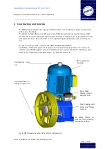
Procedure:
1.
Motor:
Connection to the power supply must comply with the wiring diagram in the motor terminal
box (see appendix for the motor wiring diagram).
Should an alternative wiring exit be required, unscrew the internal screws in order to turn the
terminal box. Exercise due care when detaching and fastening the fine temperature monitor-
ing wires.
2.
Frequency converter:
Connection and setup to the OMS elevator machine must comply with the instructions sup-
plied with the converter. Contact the frequency converter manufacturer should the need arise.
3.
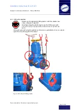
Incremental encoder:
The incremental encoder (between motor cover and handwheel) is normally supplied with a 5
m shielded cable and a 2-row 15-pin connector to be appropriately connected to the frequen-
cy converter. The shielding is wired to the plug housing, PIN 12 and the incremental encoder.
Depending on the type of incremental encoder, the connector wiring can vary (see appendix
for encoder electrical connections).
Adapters and extensions are optionally available if other connections (e.g. 3-row, 15-pin) to
the frequency converter are required (see appendix).
Содержание Hypodrive EC 2-25 Lift
Страница 2: ......


