background image

Hardware reference

HARDWARE REFERENCE MANUAL

68

Revi

si

on 3.0

3.4

TJ1-MC__  

3.4.1

Introduction

The TJ1-MC__ is the heart of the Trajexia system. You can 
program the TJ1-MC__ with the BASIC programming language to 
control the expansion units and the servo motors attached to the 
expansion units. Refer to the Programming Manual.
There are two versions of the TJ1-MC__: The TJ1-MC04 supports 
4 axes. The TJ1-MC16 supports 16 axes.

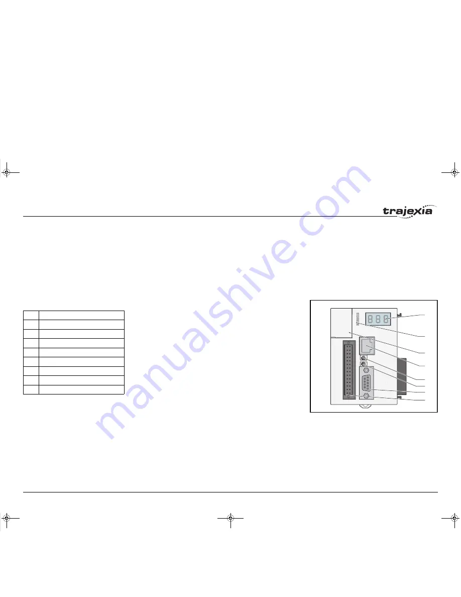
fig. 19

The TJ1-MC__ has these visible parts:

/i

A

B

C

D

E

F

G

H

Part

Description

A

LED display

B

I/O LEDs 0 - 7

C

Battery

D

Ethernet connector

E

TERM ON/OFF switch

F

WIRE 2/4 switch

G

Serial connector

H

28-pin I/O connector

I51E-EN-03.book  Seite 68  Donnerstag, 28. Juni 2007  1:05 13

Содержание TJ1-FL02

Страница 1: ...ular purpose or non infringement In a jurisdiction where the exclusion of implied warranties is not valid the exclusion shall be deemed to be replaced by such valid exclusion which most closely matches the intent and purpose of the original exclusion Omron Europe BV and or its subsidiary and affiliated companies reserve the right to make any changes to the products their specifications data at its...

Страница 2: ...if not avoided will result in death or serious injury WARNING Indicates a potentially hazardous situation which if not avoided could result in death or serious injury Caution Indicates a potentially hazardous situation which if not avoided may result in minor or moderate injury or property damage OMRON 2007 All rights reserved No part of this publication may be reproduced stored in a retrieval sys...

Страница 3: ... C71080001 Describes the installation and operation of the MECHA TROLINK II application mod ule Sigma III with MECHATRO LINK interface manual SIEP S800000 11 Describes the installation and operation of Sigma III servo drives with MECHATRO LINK interface V7 Inverter TOEP C71060605 02 OY Describes the installation and operation of V7 inverters F7Z Inverter TOE S616 55 1 OY Describes the installation...

Страница 4: ..._ to Trajexia Tools software Refer to the Programming Manual Open the terminal window and type the following commands Type PRINT VERSION in the terminal window The version parameter returns the current firmware version number of the motion controller Type PRINT FPGA_VERSION SLOT 1 in the terminal window The parameter returns the current FPGA version number of the TJ1 MC__ Functionality TJ1 MC__ Fi...

Страница 5: ...20 2 2 3 EG control 22 2 2 4 Other operations 25 2 3 Servo system principles 27 2 4 Trajexia system architecture 30 2 5 Cycle time 31 2 6 Program control and multi tasking 37 2 7 Motion sequence and axes 40 2 7 1 Profile generator 41 2 7 2 Position loop 41 2 7 3 Axis sequence 41 2 7 4 Type of axis 41 2 8 Motion buffers 48 2 9 Mechanical system 50 3 Hardware reference 51 3 1 Introduction 51 3 1 1 T...

Страница 6: ...a II series 85 3 5 7 MECHATROLINK II Servo Drivers Junma series 92 3 5 8 MECHATROLINK II Inverter V7 98 3 5 9 MECHATROLINK II Inverter F7 and G7 102 3 5 10 MECHATROLINK II digital I O slaves 107 3 5 11 MECHATROLINK II 4 Channel analogue input module 117 3 5 12 MECHATROLINK II 2 Channel analogue output module 123 3 5 13 MECHATROLINK II repeater 128 3 6 TJ1 PRT 131 3 6 1 Introduction 131 3 6 2 LEDs ...

Страница 7: ...escription 139 3 8 3 TJ1 FL02 connections 140 3 8 4 TJ1 FL02 specifications 146 3 8 5 Incremental encoder 147 3 8 6 Absolute encoder 149 3 8 7 Stepper 153 3 8 8 Registration 153 3 8 9 Hardware PSWITCH 154 3 8 10 TJ1 FL02 box contents 154 A Differences between Sigma II and Junma 162 I51E EN 03 book Seite 7 Donnerstag 28 Juni 2007 1 05 13 ...

Страница 8: ...r is being supplied Doing so may result in electric shock WARNING Never short circuit the positive and negative terminals of the bat teries charge the batteries disassemble them deform them by applying pressure or throw them into a fire The batteries may explode combust or leak liquid WARNING Fail safe measures must be taken by the customer to ensure safety in the event of incorrect missing or abn...

Страница 9: ...tion Caution Pay careful attention to the polarity when wiring the DC power supply A wrong connection may cause malfunction of the system Caution Tighten the screws on the terminal block of the Power Supply Unit to the torque specified in this manual Loose screws may result in burning or malfunction Caution Do not operate the Unit in any of the following locations Doing so may result in malfunctio...

Страница 10: ...ay result in an unexpected operation Caution Always use the power supply voltage specified in this manual An incorrect voltage may result in malfunction or burning Caution Take appropriate measures to ensure that the specified power with the rated voltage and frequency is supplied Be particularly careful in places where the power supply is unstable An incorrect power supply may result in malfuncti...

Страница 11: ...rque may result in malfunction Caution Leave the dust protective label attached to the Unit when wiring Removing the dust protective label may result in malfunction Caution Remove the dust protective label after the completion of wiring to ensure proper heat dissipation Leaving the dust protective label attached may result in malfunc tion Caution Use crimp terminals for wiring Do not connect bare ...

Страница 12: ... In environments that are subject to noise use a system with shielded twisted pair STP cable and hubs suitable for an FA environment Do not install twisted pair cables with high voltage lines Do not install twisted pair cables near devices that generate noise Do not install twisted pair cables in locations that are subject to high humidity Do not install twisted pair cables in locations subject to...

Страница 13: ...e installed The customer must therefore perform final checks to confirm that devices and the over all machine conform to EMC standards Low Voltage Directive Always ensure that devices operating at voltages of 50 to 1 000 VAC or 75 to 1 500 VDC meet the required safety standards 1 7 2 Conformance to EC Directives The Trajexia Motion Controllers comply with EC Directives To ensure that the machine o...

Страница 14: ...ion of the physical axes The available settings are 0 5ms 1ms or 2ms Cycle time Is the time needed to execute one complete cycle of operations in the TJ1 MC__ The cycle time is divided in 4 time slices of equal time length called CPU Tasks The cycle time is 1ms if SERVO_PERIOD 0 5ms or 1ms and 2ms if the SERVO_PERIOD 2ms AXIS TYPE AXIS TYPE AXIS CONTROL LOOP Position Loop Position Loop Buffer prof...

Страница 15: ...s 13 and 14 are High priority processes First the process priority High or Low and then the process number from high to low will define to which CPU task the process will be assigned CPU task Operation First CPU task Motion Sequence Low priority process Second CPU task High priority process Third CPU task Motion Sequence only if SERVO_PERIOD 0 5ms LED Update High priority process Fourth CPU task E...

Страница 16: ...pecifies the distances of travelling can be freely defined for each axis separately The conversion is performed through the use of the unit conversion factor which is defined by the UNITS axis parameter The origin point of the coordinate system can be determined using the DEFPOS command This command re defines the current position to zero or any other value fig 2 A move is defined in either absolu...

Страница 17: ...nate of 100 and axis no 1 B coordinate of 50 If the speed parameter is set to be the same for both axes and the acceleration and deceleration rate are set sufficiently high the movements for axis 0 and axis 1 will be as shown in the figure At start both the axis 0 and axis 1 moves to a coordinate of 50 over the same duration of time At this point axis 1 stops and axis 0 continues to move to a coor...

Страница 18: ... been set to 10 m s2 The total distance travelled is the sum of distances travelled during the acceleration constant speed and deceleration segments Suppose the distance moved by the MOVE command is 40 m the speed profile is given by the figure fig 5 The two speed profiles in these figures show the same movement with an acceleration time respectively a deceleration time of 2 seconds Again Axis A i...

Страница 19: ...s The FORWARD and REVERSE commands can be used to start a continuous movement with constant speed on a certain axis The FORWARD command moves the axis in positive direction and the REVERSE command in negative direction For these commands also the axis parameters ACCEL and SPEED apply to specify the acceleration rate and demand speed Acceleration time Acceleration distance Deceleration time Deceler...

Страница 20: ... and RAPIDSTOP cancels moves on all axes The deceleration rate is set by DECEL 2 2 2 CP control Continuous Path control enables to control a specified path between the start and end position of a movement for one or multiple axes The TJ1 MC__ supports the following operations Linear interpolation Circular interpolation CAM control I51E EN 03 book Seite 20 Donnerstag 28 Juni 2007 1 05 13 ...

Страница 21: ... have multiple arguments to specify the relative or absolute move for each axis Consider the three axis move in a 3 dimensional plane in the figure It corresponds to the MOVE 50 50 50 command The speed profile of the motion along the path is given in the diagram The three parameters SPEED ACCEL and DECEL that determine the multi axis movement are taken from the corresponding parameters of the base...

Страница 22: ...E command the ACCEL DECEL and SPEED variables associated with the base axis determine the speed profile along the circular move CAM control fig 9 Additional to the standard move profiles the TJ1 MC__ also provides a way to define a position profile for the axis to move The CAM command moves an axis according to position values stored in the TJ1 MC__ Table array The speed of travelling through the ...

Страница 23: ... a physical gearbox connecting them This can be done using the CONNECT command in the program In the command the ratio and the axis to link to are specified In the figure A is the Master axis and B is the CONNECT axis i A B 2 1 1 1 1 2 Axes Ratio CONNECT command 0 1 1 1 CONNECT 1 0 AXIS 1 2 1 CONNECT 2 0 AXIS 1 1 2 CONNECT 0 5 0 AXIS 1 I51E EN 03 book Seite 23 Donnerstag 28 Juni 2007 1 05 13 ...

Страница 24: ...ke connecting two axes through a cam In the figure A is the Master axis 0 position and B is the CAMBOX Axis 1 position Linked move fig 12 The MOVELINK command provides a way to link a specified move to a master axis The move is divided into an acceleration deceleration and constant speed part and they are specified in master link distances This can be particularly useful for synchronizing two axes...

Страница 25: ...d axis will consists of all movements of the actual axis plus the additional movements of the master axis In the figure A is the time axis and B is the speed axis 2 2 4 Other operations Canceling moves In normal operation or in case of emergency it can be necessary to cancel the current movement from the buffers When the CANCEL or RAPIDSTOP commands are given the selected axis respectively all axe...

Страница 26: ...dware This position can then be used to correct possible error between the actual position and the desired position The print registration is set up by using the REGIST command The position is captured in hardware and therefore there is no software overhead and no interrupt service routines eliminating the need to deal with the associated timing issues Merging moves fig 14 If the MERGE axis parame...

Страница 27: ...f the servo system as used in the TJ1 MC__ 1 The TJ1 MC__ performs actual position control The main input of the controller is the Following Error which is the calculated difference between the demand position and the actual measured position 2 The Position Controller calculates the required speed reference output determined by the Following Error and possibly the demanded position and the measure...

Страница 28: ...demanded and measured position The demand position the measured position and the Following Error are represented by the axis parameters MPOS DPOS and FE Five gain values have been implemented for the user to be able to configure the correct control operation for each application C is the output signal Proportional gain The proportional gain Kp creates an output Op that is proportional to the Follo...

Страница 29: ...proportional to the change in the measured position Pm and increases system damping Oov Kov ΔPm The output speed gain can be useful for smoothing motions but will generate high Following Errors The output speed gain axis parameter is called OV_GAIN Speed feed forward gain The speed feedforward gain Kvff produces an output Ovff that is proportional to the change in demand position Pd and minimizes ...

Страница 30: ...ror handling 2 4 3 Motion buffers Motion buffers are the link between the BASIC commands and the Axis control loop When a BASIC motion command is executed the command is stored in one of the buffers During the next motion sequence the profile generator executes the movement according to the information in the buffer When the movement is finished the motion command is removed from the buffer 2 4 4 ...

Страница 31: ... take place within the cycle time depend on the setting of the SERVO_PERIOD parameter The SERVO_PERIOD parameter is a Trajexia parameter that must be set according to the system configuration The factory setting is 1ms SERVO_PERIOD 1000 A change is set only after a restart of the TJ1 MC__ Cycle time 1ms 250μs 1 2 3 4 Cycle time 2 ms 500μs 1 2 3 4 CPU task Operation First CPU task Motion Sequence L...

Страница 32: ...e for the program execution High priority programs run faster Note Only the Sigma III servo driver supports 0 5ms transmis sion cycle CPU task 1 Motion sequence Low priority task 0 1 2 3 CPU task 2 High priority task 13 14 CPU task 3 LED refresh High priority task 13 14 CPU task 4 Communication Motion sequence 1ms CPU task 1 Motion sequence Low priority task 0 1 2 3 CPU task 2 High priority task 1...

Страница 33: ... pulse and slice bus couplers as axes You must obey the most restrictive rules when you set the SERVO_PERIOD parameter An incorrect value of the SERVO_PERIOD parameter results in an incorrect detection of the MECHATROLINK II devices The most restrictive rules are given in the tables below For each unit the table lists the maximum number of devices the unit can control at the given SERVO_PERIOD set...

Страница 34: ...RIOD 1ms TJ1 MC__ Supports 0 5ms SERVO_PERIOD with 3 axes TJ1 MC__ Supports 0 5ms SERVO_PERIOD with 3 devices Sigma II supports 1ms SERVO_PERIOD This is the limiting factor 2 0 ms 16 axes 5 axes 16 devices 4 devices 8 non axis devices 8 non axis devices SERVO_PERIOD TJ1 MC16 TJ1 MC04 TJ1 ML16 TJ1 ML04 I51E EN 03 book Seite 34 Donnerstag 28 Juni 2007 1 05 13 ...

Страница 35: ...h 8 devices Sigma II supports 1ms SERVO_PERIOD Address 49 Axis 0 Axis 8 Axis 1 Axis 9 Axis 2 Axis 10 Axis 3 Axis 11 Axis 4 Axis 12 Axis 5 Axis 13 Axis 6 Axis 14 Axis 7 Axis 15 Address 4A Address 4B Address 4C Address 4D Address 4E Address 4F Address 50 Terminator Servo Drive Address 41 Address 42 Address 43 Address 44 Address 45 Address 46 Address 47 Address 48 Terminator I51E EN 03 book Seite 35 ...

Страница 36: ... TJ1 ML16 supports 2 0ms SERVO_PERIOD with 12 devices This is the limiting factor Sigma II supports 1 0ms SERVO_PERIOD SI T supports 1ms MECHATROLINK II I Os support 1 0ms Address 41 Address 42 Address 43 Address 44 Address 45 Address 46 Address 47 Address 48 Address 61 Address 21 Address 62 Address 63 I O Memory Allocations 0 31 32 95 96 159 160 I51E EN 03 book Seite 36 Donnerstag 28 Juni 2007 1 ...

Страница 37: ... 0 5ms SERVO_PERIOD 2 axes each module Sigma II supports 1 0ms SERVO_PERIOD 2 6 Program control and multi tasking The Trajexia system has program processes and multi tasking control 2 6 1 Program control The Trajexia system can control 14 processes that are written as BASIC programs When the program is set to run the program is executed Processes 1 to 12 are low priority 13 and 14 are high priorit...

Страница 38: ...LT period High priority processes B are executed in the high Task HT periods fig 27 External communication that are not related to the motion network are updated in the communications COMS period in the fourth CPU task Trajexia can control up to 14 programs at the same time In contrast to low priority processes a high priority process is always available for execution during two of the four CPU ta...

Страница 39: ...gh priority process 14 Both HT periods are reserved for this process The low priority processes 3 2 1 and 0 are executed in the LT period one process per cycle time In the lower example there are no high priority processes Therefore the HT periods can be used for the low priority processes The LT period is also used for the low priority processes 2 3 14 13 14 13 14 3 COMS 1ms 14 2 COMS COMS 1ms 14...

Страница 40: ...0 Every axis has the general structure as shown in fig 29 The motion sequence which will be executed at the beginning of each servo period will contain the following elements 1 Transfer any moves from BASIC process buffers to motion buffers see section 2 8 2 Read digital inputs 3 Load moves See note 4 Calculate speed profile See note 5 Calculate axis positions See note 6 Execute position servo for...

Страница 41: ...s 2 7 3 Axis sequence If SERVO OFF for one axis the motion commands for that axis are ignored If the Following Error FE in one axis exceeds the parameter value FELIMIT then the next action occurs WDOG is set to OFF and all axes stop SERVO for the axis that causes the error goes to OFF The current move is Cancelled and removed from the buffer 2 7 4 Type of axis i Basic Program MOVE 1000 Profile gen...

Страница 42: ...se and direction outputs Position loop is in the driver TJ1 FL02 sends pulses and receives no feed back 44 Servo axis Default Encoder Analogue servo Position loop is in the TJ1 MC__ The TJ1 FL02 sends speed reference and receives position from an incremental encoder 45 Encoder out put The same as stepper but with the phase differ ential outputs emulating an incremental encoder 46 Absolute Tam agaw...

Страница 43: ...ON DEMAND POSITION Profile generator Profile generator Position loop Following error Speed command Position loop Demanded position Measured position Following error Speed command NOP ML II Positon command Speed Loop Torque Loop M M E E TJ1 MC16 TJ1 ML16 SERVO Position Loop SERVO SERVO Trajexia Position Loop is desactivated Gains are not used OFF OFF Note Although MPOS and FE are updated the real v...

Страница 44: ..._REF command 0x40000000 is the maximum torque of the servomotor Profile generator Profile generator Position loop Following error Speed command Position loop Demanded position Measured position Following error Speed command S_REF ML II Speed command Speed Loop Torque Loop M M E E TJ1 MC16 TJ1 ML16 SERVO SERVO_AXIS n ON OFF SERVO SERVO SERVO OFF OFF Profile generator Profile generator Position loop...

Страница 45: ...eed reference output and incremental encoder feedback input The position loop is closed in the TJ1 MC__ which sends the resulting speed reference to the axis fig 36 With SERVO OFF the position of the external incremental encoder is read The analogue output can be set with BASIC commands only and can be used for general purposes Profile generator Following Error Demanded Position Measured Position ...

Страница 46: ...poses Absolute EnDat ATYPE 47 With SERVO ON this is an axis with analogue speed reference output and absolute EnDat feedback The position loop is closed in the TJ1 MC__ and the resulting speed reference is sent to the axis With SERVO OFF the position of the external absolute EnDat is read The analogue output can be set with BASIC commands only and can be used for general purposes Absolute SSI ATYP...

Страница 47: ... axes Set the speed with S_REF 41 1 Position MECHATROLINK II The position loop is closed in Trajexia This gives lower performance than closing the position loop in the Servo Driver 42 0 Torque MECHATROLINK II Recommended mode for torque control with MECHA TROLINK II axes Set the torque with T_REF 42 1 Postion via torque MECHATROLINK II The position loop is closed in Trajexia The output of the posi...

Страница 48: ...struction is loaded into the process buffer and distributed to the corresponding axis buffer in the next motion sequence If a fourth motion instruction is executed and the three buffers are full the BASIC program stops execution until a process buffer is free for use DEMAND POSITION BASIC PROGRAM MOVE 500 MOVE 1000 CONNECT 1 1 BASIC PROGRAM MOVE 500 MOVE 1000 CONNECT 1 1 CONNECT 1 1 AXIS 2 PROCESS...

Страница 49: ... sent movements are finished the buffer empties BASIC PROGRAM MOVE 500 MOVE 1000 DATUM 3 MOVE 200 NTYPE MOVE 200 MTYPE DATUM 3 BUFFER MOVE 500 MOVE 1000 DATUM 3 BASIC PROGRAM MOVE 500 MOVE 1000 DATUM 3 MOVE 200 NTYPE MOVE 200 MTYPE DATUM 3 BASIC PROGRAM MOVE 500 MOVE 1000 DATUM 3 MOVE 200 NTYPE IDLE MTYPE MOVE 200 BUFFER MOVE 500 MOVE 1000 DATUM 3 MOVE 200 BASIC PROGRAM MOVE 500 MOVE 1000 DATUM 3 ...

Страница 50: ...aximum dynamic of the motor driver combination 2 9 2 Rigidity If a machine is more rigid and less elastic you can set higher gains without vibration and you can reach higher dynamic and lower Following Error 2 9 3 Resonant frequency A mechanical system has at least one resonant frequency If you excite your mechanical system to the resonant frequency it starts oscillating For motion systems it is b...

Страница 51: ...l and interpolation all via simple motion commands Trajexia offers control of up to 16 axes over a MECHATROLINK II motion bus or traditional analogue or pulse control with independent position speed or torque control for every axis And its powerful motion instruction set makes programming intuitive and easy You can select from a wide choice of best in class rotary linear and direct driver servos a...

Страница 52: ...s control of up to 16 servos inverters or I Os while allowing complete transparency across the whole system MECHATROLINK II offers the communication speed and time accuracy essential to guarantee perfect motion control of servos The motion cycle time is selectable between 0 5 ms 1 ms or 2 ms TJ1 FL02 Flexible Axis Unit The TJ1 FL02 allows full control of two actuators via an analogue output or pul...

Страница 53: ...ully accessible from the Ethernet connection One minute Trajexia Tools includes advanced debugging tools including trace and oscilloscope functions to ensure efficient operation and minimum downtime The servos inverters and I Os connected to the MECHATROLINK II motion bus are automatically identified and configured allowing you to set up your system in minutes 3 1 3 This manual This Hardware Refer...

Страница 54: ...Terminator Unit The expansion units unit numbers 0 6 can be arranged in any order The TJ1 MC__ autodetects all units A Trajexia system with a TJ1 MC16 can include 0 to 4 TJ1 ML__ units MECHATROLINK II Master Unit 0 to 7 TJ1 FL02 units 0 or 1 TJ1 PRT PROFIBUS DP Slave Unit or TJ1 DRT units DeviceNet Slave Unit 1 A Trajexia system with a TJ1 MC04 can include 0 to 4 TJ1 ML__ units 0 to 3 TJ1 FL02 uni...

Страница 55: ...ration A Power supply B TJ1 MC__ C TJ1 ML__ D Sigma II Servo Driver E NS115 MECHATROLINK II Interface Unit F Sigma II servo motor G TJ1 TER 0 1 2 3 4 5 6 7 CN3 CN1 TER M ON O FF WIR E 2 4 CN2 MC 16 OMR ON MOTI ON CONT ROLL ER RUN 8F CN1 ML1 6 G C B A F E D I51E EN 03 book Seite 55 Donnerstag 28 Juni 2007 1 05 13 ...

Страница 56: ... and the TJ1 TER push the clips A on top and bottom of the TJ1 TER to the front 4 Disconnect the TJ1 TER from the TJ1 MC__ fig 6 5 Push the clips A on top and bottom of all the units to the front 0 1 2 3 4 5 6 7 CN3 CN1 TER M ON OFF WIR E 2 4 CN2 MC 16 OMR ON MOT ION CON TROL LER A 0 1 2 3 4 5 6 7 CN3 CN1 TER M ON OFF WIR E 2 4 CN2 MC 16 OMRON MOT ION CON TROLLER A I51E EN 03 book Seite 56 Donners...

Страница 57: ...wer Supply Unit B fig 8 7 Push the clips A on top and bottom to the rear 0 1 2 3 4 5 6 7 CN3 CN1 TER M ON OFF WIR E 2 4 CN2 MC 16 OMRON MOT ION CON TROLLER C B 0 1 2 3 4 5 6 7 CN3 CN1 TER M ON OFF WIR E 2 4 CN2 MC 16 OMR ON MOT ION CON TROLLER A I51E EN 03 book Seite 57 Donnerstag 28 Juni 2007 1 05 13 ...

Страница 58: ...rovide proper cooling The recommended DIN rail is of type PFP 100N2 PFP 100N or PFP 50N 12 Push all the clips D up on all units 13 After you complete the wiring of the units remove the protection labels from the units 0 1 2 3 4 5 6 7 CN3 CN1 TER M ON O FF WIR E 2 4 CN2 MC 16 OMR ON MOT ION CON TROL LER RUN 8F CN1 ML1 6 A 0 1 2 3 4 5 6 7 CN3 CN1 TER M ON O FF WIR E 2 4 CN2 MC 16 OMR ON MOTI ON CONT...

Страница 59: ...sitions Upside down With the top side forward With the bottom forward Vertically 0 1 2 3 4 5 6 7 CN3 CN1 TERM ON OFF WIRE 2 4 CN2 MC16 OMRON MOTION CONTROLLER RUN 8F CN1 ML16 0 1 2 3 4 5 6 7 CN3 CN1 TERM ON OFF WIRE 2 4 CN2 MC16 OMRON MOTION CONTROLLER RUN 8F CN1 ML16 I51E EN 03 book Seite 59 Donnerstag 28 Juni 2007 1 05 13 ...

Страница 60: ...2 15 When you design a cabinet for the units make sure that the cabinet allows at least 20 mm of space around the units to provide sufficient airflow We advise to allow at least 100 mm of space around the units I51E EN 03 book Seite 60 Donnerstag 28 Juni 2007 1 05 13 ...

Страница 61: ...midity 90 max with no condensation Atmosphere No corrosive gases Vibration resistance 10 to 57 Hz 0 075 mm amplitude 57 to 100 Hz Acceleration 9 8 m s2 in X Y and Z directions for 80 minutes Shock resistance 147 m s2 3 times each X Y and Z directions Insulation resistance 20 MΩ Dielectric strength 500 VAC Protective structure IP20 International standards CE EN 61131 2 cULus Lloyds cULus approval p...

Страница 62: ...L 62 Revision 3 0 3 2 3 Unit dimensions The dimensions for the units of the Trajexia system are as follows Trajexia motion controller fig 13 All measurements are in mm 62 65 71 70 3 90 94 I51E EN 03 book Seite 62 Donnerstag 28 Juni 2007 1 05 13 ...

Страница 63: ...Hardware reference HARDWARE REFERENCE MANUAL 63 Revision 3 0 Trajexia units fig 14 All measurements are in mm 31 39 9 70 3 90 94 I51E EN 03 book Seite 63 Donnerstag 28 Juni 2007 1 05 13 ...

Страница 64: ...he modules that are mounted Allow sufficient depth in the control cabinet 3 2 4 Wire the Weidmüller connectors The TJ1 MC__ and the TJ1 FL02 units have Weidmüller connectors These units come with Weidmüller contra connectors To wire the Weidmüller contra connectors do these steps 62 65 29 7 31 45 90 94 PA202 70 30 81 60 to 89 0 mm 90 94 I51E EN 03 book Seite 64 Donnerstag 28 Juni 2007 1 05 13 ...

Страница 65: ...cation Wire types 0 14 1 0 mm2 Solid stranded or stranded with ferrule Crimp ferrules according to DIN46228 1 Crimp ferrules wit plastic collar according to DIN46228 4 With recommended tool Weidmüller PZ6 Insertion tool 2 5 mm flat bladed screwdriver Recommended ferrule types Weidmüller AEH H0 14 12 AEH H0 25 12 AEH H0 34 12 Stripping length 7 mm without ferrules tolerance 1 mm 0 mm 10 mm with fer...

Страница 66: ...Line earth 1 Line earth 1 The line earth terminal C is a noise filtered neutral terminal If noise is a significant source of errors or electrical shocks are a problem connect the line earth terminal to the earth terminal D and connect both to earth with a resistance of less than 100 Ohms Line earth D Earth 2 Earth 2 To help prevent electrical shock connect the earth terminal D to earth with a resi...

Страница 67: ...on or fire Power Supply Unit Input voltage Maximum current consumption Output power 5 V group 24 V group CJ1W PA202 110 240 VAC 2 8 A 0 4 A 14 W CJ1W PA205R 110 240 VAC 5 0 A 0 8 A 25 W CJ1W PD025 24 VDC 5 0 A 0 8 A 25 W Caution The amount of current and power that can be supplied to the sys tem is limited by the capacity of the Power Supply Unit Refer to this table when designing your system so t...

Страница 68: ...rvo motors attached to the expansion units Refer to the Programming Manual There are two versions of the TJ1 MC__ The TJ1 MC04 supports 4 axes The TJ1 MC16 supports 16 axes fig 19 The TJ1 MC__ has these visible parts i A B C D E F G H Part Description A LED display B I O LEDs 0 7 C Battery D Ethernet connector E TERM ON OFF switch F WIRE 2 4 switch G Serial connector H 28 pin I O connector I51E EN...

Страница 69: ...m to the power supply IP address Shows 4 times when you connect an Ethernet cable to the Ethernet connector of the TJ1 MC__ and to a PC RUN When the TJ1 MC__ operates a Servo Driver OFF When the TJ1 MC__ does not operate a Servo Driver ERR code When an error occurs in the Trajexia system The code is the error code Refer to troubleshooting chapter in the Programming Manual I51E EN 03 book Seite 69 ...

Страница 70: ...rectly to the TJ1 MC__ and not via a hub or any other network device the PC must have a fixed IP address The TJ1 MC__ automatically detects when a cable is connected to the Ethernet connector BASIC installation precautions Make sure that the Ethernet system is to the IEEE Std 802 3 standard Do not install the Ethernet system near a source of noise Environmental precautions UTP cables are not shiel...

Страница 71: ...he communication standard of the serial connection and the position of the TJ1 MC__ in the network i 9 8 7 6 5 4 3 2 1 Pin Communication Connection 1 RS422 RS485 Tx 2 RS232 Tx 3 RS232 Rx 4 N C N C 5 N C N C 6 RS422 RS485 Rx 7 RS422 RS485 Tx 8 RS422 RS485 Rx 9 RS232 0 V Communication standard Position of the TJ1 MC__ Setting of the TERM ON OFF switch RS422 or RS485 First or last Left on RS422 or RS...

Страница 72: ...r the RS422 485 serial connection To use one of the communication standards do this i A B C D E F G H Communication standard How to select it RS422 Set the WIRE 2 4 switch right RS485 Set the WIRE 2 4 switch left Note In RS485 mode the transmit pair is connected to the receive pair I51E EN 03 book Seite 72 Donnerstag 28 Juni 2007 1 05 13 ...

Страница 73: ...on Pin Connection 1 0 V input common 2 0 V input common 3 Input 0 4 Input 1 5 Input 2 6 Input 3 7 Input 4 8 Input 5 9 Input 6 10 Input 7 11 Input 8 12 Input 9 13 Input 10 14 Input 11 15 Input 12 16 Input 13 17 Input 14 18 Input 15 19 Output 8 20 Output 9 21 Output 10 22 Output 11 23 Output 12 24 Output 13 25 Output 14 26 Output 15 27 0 V output common 28 24V Power supply Input for the Outputs I51E...

Страница 74: ...y of the input in 13 pin16 of the 28 pin I O connector LED label n 0 n 1 n 2 n 3 n 4 n 5 n 6 n 7 0 IN 0 IN 8 IN 16 IN 24 OUT 0 OUT 8 OUT 16 OUT 24 1 IN 1 IN 9 IN 17 IN 25 OUT 1 OUT 9 OUT 17 OUT 25 2 IN 2 IN 10 IN 18 IN 26 OUT 2 OUT 10 OUT 18 OUT 26 3 IN 3 IN 11 IN 19 IN 27 OUT 3 OUT 11 OUT 19 OUT 27 4 IN 4 IN 12 IN 20 IN 28 OUT 4 OUT 12 OUT 20 OUT 28 5 IN 5 IN 13 IN 21 IN 29 OUT 5 OUT 13 OUT 21 OU...

Страница 75: ...put O8 to O15 specifications i The timings are dependant upon the MC16 s servo period and include physical delays in the output circuit TJ 1 MC 16 3 0V Input 0V common for Input circuits External power supply 24V 1 Input Item Specification Type PNP NPN Maximum voltage 24 VDC 10 Input current 5 mA at 24 VDC ON voltage 14 4 VDC OFF voltage 5 0 VDC max TJ 1 MC 16 External power supply 24V Load 2A Fus...

Страница 76: ...d global variables are stored and real Time Clock when the power supply is off You must replace it every five years The part number of the backup battery is CJ1W BAT01 To replace the battery the power must not be off for more than five minutes to ensure no backup memory loss If the TJ1 MC__ has not been on set the unit to on for at least five minutes before you replace the battery else the capacit...

Страница 77: ...Battery backup Saving program data on the PC Trajexia Tools software manages backups on the hard disk of the PC Communication connectors 1 Ethernet connection 2 serial connections Firmware update Via Trajexia Tools software Electrical characteristics of the Ethernet connector Conforms to IEEE 802 3 100BaseT Ethernet connector RJ45 Item Specification Electrical characteristics PORT1 RS232C non isol...

Страница 78: ...e last unit 3 4 7 TJ1 MC__ box contents Safety sheet TJ1 MC__ battery included Protection label attached to the top surface of the TJ1 MC__ TJ1 TER attached to the TJ1 MC__ Parts for a serial connector Parts for an I O connector Two metal DIN rail clips to prevent the Trajexia system from sliding off the rail White clip to replace the yellow clip of the Power Supply Unit I51E EN 03 book Seite 78 D...

Страница 79: ...be fig 29 Servo Drivers Inverters I Os The TJ1 ML__ has these visible parts i Together the TJ1 ML__ and its devices form a serial network The first unit in the network is the TJ1 ML__ One TJ1 ML16 can control 16 devices One TJ1 ML04 can control 4 devices RUN 8F ML16 CN1 A B Part Description A LED indicators B CN1 MECHATROLINK II bus connector I51E EN 03 book Seite 79 Donnerstag 28 Juni 2007 1 05 1...

Страница 80: ...he TJ1 ML__ to a MECHATROLINK II network The MECHATROLINK II network must always be closed by the MECHATROLINK II terminator Label Status Description run off Start up test failed Unit not operational Operation stopped Fatal error on Start up test successful Normal operation BF off Normal operation on A fault in the MECHATROLINK II bus Reserved RUN 8F ML16 CN1 A I51E EN 03 book Seite 80 Donnerstag ...

Страница 81: ...1 Example 1 1 x TJ1 MC__ 1 x TJ1 ML__ 3 x Sigma II Servo Driver 1 x MECHATROLINK II terminator Address 43 Axis 2 Axis 3 Axis 4 Address 44 Address 45 Terminator Servo Drive All Mechatrolink Adresses are numbered 4x up to 16 per unit I51E EN 03 book Seite 81 Donnerstag 28 Juni 2007 1 05 13 ...

Страница 82: ... Axis 0 Axis 8 Axis 1 Axis 9 Axis 2 Axis 10 Axis 3 Axis 11 Axis 4 Axis 12 Axis 5 Axis 13 Axis 6 Axis 14 Axis 7 Axis 15 Address 4A Address 4B Address 4C Address 4D Address 4E Address 4F Address 50 Terminator Servo Drive Address 41 Address 42 Address 43 Address 44 Address 45 Address 46 Address 47 Address 48 Terminator I51E EN 03 book Seite 82 Donnerstag 28 Juni 2007 1 05 13 ...

Страница 83: ... Driver 1 x Inverter 3 x I O units 1 x MECHATROLINK II terminator Address 41 Axis 0 Address 21 Address 61 Address 62 Address 63 I O Memory Allocations I O UNITS I O Addresses are numbered 6x valid range 60 to 6F I O Address selected on DIP Switches INVERTERS All Inverter Addresses are numbered 2x valid range 20 to 2F Terminator 0 31 32 95 96 159 160 223 224 I51E EN 03 book Seite 83 Donnerstag 28 J...

Страница 84: ... and 64 point digital output 24 VDC sinking JEPMC IO2310 64 point digital input and 64 point digital output 24 VDC sourcing JEPMC IO2330 Analogue input 10V to 10 V 4 channels JEPMC AN2900 Analogue output 10 V to 10 V 2 channels JEPMC AN2910 MECHATROLINK II cables 0 5 meter JEPMC W6003 A5 1 meters JEPMC W6003 01 3 meters JEPMC W6003 03 5 meters JEPMC W6003 05 10 meters JEPMC W6003 10 20 meters JEPM...

Страница 85: ...he TJ1 ML__ The TJ1 MC__ sends either the target position speed or torque to the receiver depending on the axis type Other functionality of the Servo Driver is available but refreshed at slower rate A Servo Driver is considered an axis by the TJ1 MC__ When you connect a servo to the Trajexia the parameter does not change automatically so depending on the application you may have to change values T...

Страница 86: ... Alarm Red Lit an alarm occurred Not lit no alarm active Ready Green Lit communication active Not lit no communication in progress 1 ON OFF 2 3 4 Dipswitch Function Set ting Description 1 Baud rate on 10 Mbps 2 Data length on 32 byte data transmission 3 Address range off Addresses 40 4F on Addresses 50 5F 4 Maintenance Reserved off Must always be set to off on is not used I51E EN 03 book Seite 86 ...

Страница 87: ...NS115 i Do not use the addresses 40 and 51 5F Use only the addresses 41 50 Rotary switch number Dipswitch 3 Station address Axis in motion controller 1 off 41 0 2 off 42 1 3 off 43 2 4 off 44 3 5 off 45 4 6 off 46 5 7 off 47 6 8 off 48 7 9 off 49 8 A off 4A 9 B off 4B 10 C off 4C 11 D off 4D 12 E off 4E 13 F off 4F 14 0 on 50 15 I51E EN 03 book Seite 87 Donnerstag 28 Juni 2007 1 05 13 ...

Страница 88: ...ll closed encoder connector CN4 is for connecting a full closed encoder that is the position is controlled based in one external encoder and the speed and torque loop based in the motor encoder This is used when you install the motor in machines where you have to measure directly on the load because either There is slip or backlash in the mechanical transmission The precision required is very high...

Страница 89: ...G0V FB FB FC FC A A GND B B Z Z CN4 1 PG0V Signal ground 2 PG0V Signal ground 3 PG0V Signal ground 4 5 6 7 8 9 10 11 12 13 14 FC Phase C input 15 FC Phase C input 16 FA Phase A input 17 FA Phase A input 18 FB Phase B input 19 FB Phase B input 20 Note Make sure that shielded cable is used and that the shield is connected to the connector shell I51E EN 03 book Seite 89 Donnerstag 28 Juni 2007 1 05 1...

Страница 90: ...resolution Pn203 Gear ratio denominator Default 1 Absolute encoder Pn205 Number of multiturn limit Default 65535 Set to suitable value in combination with the encoder gear ratio and UNITS Full close encoder Pn002 3 0 Disabled 1 uses without Z 2 uses with Z 3 uses without Z reverse rotation 4 uses with Z reverse rotation Pn206 Number of full closed encoder pulses per revolution Default 16384 I51E E...

Страница 91: ...o Driver inputs from Trajexia is to set i For the rest of the parameters and connections refer to the Sigma II manual Parameter setting Input in Sigma II Bit in Trajexia Pn81E 4321 CN1 40 DRIVE_INPUTS bit 12 CN1 41 DRIVE_INPUTS bit 13 CN1 42 DRIVE_INPUTS bit 14 CN1 43 DRIVE_INPUTS bit 15 Pn511 654X CN1 44 DRIVE_INPUTS bit 06 CN1 45 DRIVE_INPUTS bit 07 CN1 46 DRIVE_INPUTS bit 08 I51E EN 03 book Sei...

Страница 92: ...s connectors C CN1 I O signal connector D CN2 Encoder input connector E SW1 Rotary switch for MECHATROLINK II address settings F SW2 Dipswitches for MECHATROLINK II communication settings G RDY Servo status indicator H ALM Alarm indicator I COM MECHATROLINK II communication status indicator J CNA Connector for power supply K CNB Connector for servo motor LED Description COM Lit MECHATROLINK II com...

Страница 93: ...settings i 1 2 3 4 Dipswitch Function Setting Description 1 Reserved ON Must always be set to ON OFF is not used 2 Data length ON 32 bytes 3 Address range OFF Addresses 40 4F ON Addresses 50 5F 4 Filter setting OFF Set the filter with the FIL rotary switch ON Set the filter with Pn00A I51E EN 03 book Seite 93 Donnerstag 28 Juni 2007 1 05 13 ...

Страница 94: ...tion address to it i Do not use the addresses 40 and 51 5F Use only the addresses 41 50 Rotary switch number Dipswitch 3 Station address Axis in motion controller 1 off 41 0 2 off 42 1 3 off 43 2 4 off 44 3 5 off 45 4 6 off 46 5 7 off 47 6 8 off 48 7 9 off 49 8 A off 4A 9 B off 4B 10 C off 4C 11 D off 4D 12 E off 4E 13 F off 4F 14 0 on 50 15 I51E EN 03 book Seite 94 Donnerstag 28 Juni 2007 1 05 13...

Страница 95: ...vice or the TJ1 ML__ Use the other MECHATROLINK II connector to connect to the next MECHATROLINK II device or to connect a MECHATROLINK II terminator 8 9 10 11 12 13 14 1 2 3 4 5 6 7 Pin I O Code Signal name 1 Input EXT1 External latch 2 Input DEC Homing deceleration 3 Input N_OT Reverse run prohibit 4 Input P_OT Forward run prohibit 5 Input 24VIN External input power supply 6 Input E STP Emergenc...

Страница 96: ...w shows the pin layout for the CNA power supply connector i 2 4 6 8 10 9 7 5 3 1 Pin Signal 1 PG5V 2 PG0V GND 3 Phase A 4 Phase A 5 Phase B 6 Phase B 7 Phase Z 8 Phase U 9 Phase V 10 Phase W Shell A 4 3 2 1 N 1 2 3 4 Pin Signal Name 1 L1 Power supply terminal 2 L2 Power supply terminal 3 Regenerative unit connection terminal 4 Regenerative unit connection terminal I51E EN 03 book Seite 96 Donnerst...

Страница 97: ...vision 3 0 CNB servo motor connector fig 46 The tables below shows the pin layout for the CNB servo motor connector i A 1 2 3 4 N 1 2 3 4 Pin Signal Name 1 U Phase U 2 V Phase V 3 W Phase W 4 N C I51E EN 03 book Seite 97 Donnerstag 28 Juni 2007 1 05 13 ...

Страница 98: ...e of an AC induction motor No position control is supported via MECHATROLINK II An inverter is not considered an axis by the TJ1 MC__ The illustration shows the external appearance of the SI T V7 Unit A LED B Modular plug CN10 C Optional connector CN1 D Communications connector CN2 E Dipswitch F Rotary switch G Ground terminal H Communications connector CN2 B H G F D A C E I51E EN 03 book Seite 98...

Страница 99: ...e error ERR Red Lit Watchdog timeout error communications error or resetting hardware Red Flashing ROM check error once RAM check error twice DPRAM check error 3 times com munications ASIC self diagnosis error 4 times ASIC RAM check error 5 times sta tion address setting error 6 times Inverter model code error 7 times indicates the number of flashes Not lit No communication error or self diagnosis...

Страница 100: ...ransmission MECHATROLINK II Station address S1 3 off Set the 10th digit of the station number to 2 Invalid if the maximum number of units including the S2 of the rotary switch is 20 on Set the 10th digit of the station number to 3 Invalid if the maximum number of units including the S2 of the rotary switch is 3F Mainte nance S1 4 off Normally off1 1 For maintenance Always leave this switch off on ...

Страница 101: ...tation number Invalid if the maximum number of units including the S1 3 is 20 or 3F 1 S1 3 S2 Station number S1 3 S2 Station number off 0 Fault on 0 30 off 1 21 on 1 31 off 2 22 on 2 32 off 3 23 on 3 33 off 4 24 on 4 34 off 5 25 on 5 35 off 6 26 on 6 36 off 7 27 on 7 37 off 8 28 on 8 38 off 9 29 on 9 39 off A 2A on A 3A off B 2B on B 3B off C 2C on C 3C off D 2D on D 3D off E 2E on E 3E off F 2F o...

Страница 102: ...LINK II N4 9 Reference via MECHATROLINK II Check the manual for details about the V7 inverter 3 5 9 MECHATROLINK II Inverter F7 and G7 fig 51 The illustration shows the installation of the SI T card A SI T Card B Control terminal C 3CN Option D connector D Option CN To secure option C or D E 2CN Option C connector F 4CN Option A connector A D F E C B I51E EN 03 book Seite 102 Donnerstag 28 Juni 20...

Страница 103: ...ANUAL 103 Revision 3 0 fig 52 The illustration shows the external appearance of the SI T Card A LED B Rotary switch C Dipswitch D Communications connector E Code No F Type A C B F E D I51E EN 03 book Seite 103 Donnerstag 28 Juni 2007 1 05 13 ...

Страница 104: ...g timeout error communication error diagnosis error or resetting hardware Red Flashing ROM check error once RAM check error twice DPRAM check error 3 times commu nications ASIC self diagnosis error 4 times ASIC RAM check error 5 times station address setting error 6 times Inverter model code error 7 times indicates the number of flashes Not lit No communication error or self diagnosis error TX Gre...

Страница 105: ...ransmission MECHATROLINK II Station address S1 3 off Set the 10th digit of the station number to 2 Invalid if the maximum number of units including the S2 of the rotary switch is 20 on Set the 10th digit of the station number to 3 Invalid if the maximum number of units including the S2 of the rotary switch is 3F Mainte nance S1 4 off Normally off1 1 For maintenance Always leave this switch off on ...

Страница 106: ...igit of the station number X0H XFH Invalid if the maximum number of units including the S1 3 is 20 or 3F 1 S1 3 S2 Station number S1 3 S2 Station number off 0 Fault on 0 30 off 1 21 on 1 31 off 2 22 on 2 32 off 3 23 on 3 33 off 4 24 on 4 34 off 5 25 on 5 35 off 6 26 on 6 36 off 7 27 on 7 37 off 8 28 on 8 38 off 9 29 on 9 39 off A 2A on A 3A off B 2B on B 3B off C 2C on C 3C off D 2D on D 3D off E ...

Страница 107: ...II slave unit The digital inputs and outputs are automatically allocated by the Trajexia system according to the unit number and can be read and set by Trajexia starting from IN 32 and OP 32 Trajexia Inputs and outputs are automatically mapped starting from IN 32 and OP 32 according to the MECHATROLINK II node number In the case of existing several IO2310 units the unit with lowest node number cor...

Страница 108: ...g 59 Connect the I O Unit with external I O signals through the I O Cable Number of I O points 64 inputs and 64 outputs R Active F 1 2 3 4 5 6 7 8 9 10 11 12 13 14 15 16 17 18 19 20 21 22 23 24 25 26 27 28 29 30 31 32 Indicator Name Indicator Color Meaning when lit R Yellow Not used stays lit ACTIVE Yellow Sending data through MECHATROLINK II F Red Blown fuse 1 to 32 Yellow Input signal and output...

Страница 109: ...A4 IN30 Input 30 B4 IN29 Input 29 A5 IN28 Input 28 B5 IN27 Input 27 A6 IN26 Input 26 B6 IN25 Input 25 A7 IN24 Input 24 B7 IN23 Input 23 A8 IN22 Input 22 B8 IN21 Input 21 A9 IN20 Input 20 B9 IN19 Input 19 A10 IN18 Input 18 B10 IN17 Input 17 A11 IN16 Input 16 B11 IN15 Input 15 A12 IN14 Input 14 B12 IN13 Input 13 A13 IN12 Input 12 B13 IN11 Input 11 A14 IN10 Input 10 B14 IN09 Input 9 A15 IN08 Input 8 ...

Страница 110: ... Input 61 A5 IN60 Input 60 B5 IN59 Input 59 A6 IN58 Input 58 B6 IN57 Input 57 A7 IN56 Input 56 B7 IN55 Input 55 A8 IN54 Input 54 B8 IN53 Input 53 A9 IN52 Input 52 B9 IN51 Input 51 A10 IN50 Input 50 B10 IN49 Input 49 A11 IN48 Input 48 B11 IN47 Input 47 A12 IN46 Input 46 B12 IN45 Input 45 A13 IN44 Input 44 B13 IN43 Input 43 A14 IN42 Input 42 B14 IN41 Input 41 A15 IN40 Input 40 B15 IN39 Input 39 A16 ...

Страница 111: ...6 OUT25 Output 25 A7 OUT24 Output 24 B7 OUT23 Output 23 A8 OUT22 Output 22 B8 OUT21 Output 21 A9 OUT20 Output 20 B9 OUT19 Output 19 A10 OUT18 Output 18 B10 OUT17 Output 17 A11 OUT16 Output 16 B11 OUT15 Output 15 A12 OUT14 Output 14 B12 OUT13 Output 13 A13 OUT12 Output 12 B13 OUT11 Output 11 A14 OUT10 Output 10 B14 OUT09 Output 9 A15 OUT08 Output 8 B15 OUT07 Output 7 A16 OUT06 Output 6 B16 OUT05 Ou...

Страница 112: ...put 59 A6 OUT58 Output 58 B6 OUT57 Output 57 A7 OUT56 Output 56 B7 OUT55 Output 55 A8 OUT54 Output 54 B8 OUT53 Output 53 A9 OUT52 Output 52 B9 OUT51 Output 51 A10 OUT50 Output 50 B10 OUT49 Output 49 A11 OUT48 Output 48 B11 OUT47 Output 47 A12 OUT46 Output 46 B12 OUT45 Output 45 A13 OUT44 Output 44 B13 OUT43 Output 43 A14 OUT42 Output 42 B14 OUT41 Output 41 A15 OUT40 Output 40 B15 OUT39 Output 39 A...

Страница 113: ...r each unit if two or more units are connected fig 62 Dipswitch settings The dipswitch sets the communication parameters i The data in the parentheses indicate the MECHATROLINK II addresses Name Model Length m I O Cable JEPMC W5410 05 0 5 JEPMC W5410 10 1 JEPMC W5410 30 3 4 3 2 1 7 6 5 8 B A 9 C F E D 0 ON OFF 1 2 3 _ Display Switch No Name Status Function Reserved by system Be sure to turn it off...

Страница 114: ...ff 2 17 71h on 1 3 63h off 3 18 72h on 2 4 64h off 4 19 73h on 3 5 65h off 5 20 74h on 4 6 66h off 6 21 75h on 5 7 67h off 7 22 76h on 6 8 68h off 8 23 77h on 7 9 69h off 9 24 78h on 8 10 6Ah off A 25 79h on 9 11 6Bh off B 26 7Ah on A 12 6Ch off C 27 7Bh on B 13 6Dh off D 28 7Ch on C 14 6Eh off E 29 7Dh on D 15 6Fh off F Not used on E F I51E EN 03 book Seite 114 Donnerstag 28 Juni 2007 1 05 13 ...

Страница 115: ...C24V 24 VDC DC0V 0 VDC FG Protective ground terminal 4 7 kΩ Input Circuit 680 Ω 0 01 μF 5V Item Specifications Number of input points 64 points 32 points x 2 Input type Sinking or sourcing Isolation method Photocoupler Input voltage 24 VDC 20 4 to 28 8 VDC Input current 5 mA point on voltage current 9V min 1 6 mA min off voltage current 7V max 1 3 mA max on time off time on time 2ms off time 3 ms ...

Страница 116: ...r Output voltage 24 VDC 20 4 to 28 8 VDC Output current 50 mA point Leakage current when off 0 1 mA max on time off time on time 2 ms max off time 4 ms max Output points per com mon 16 points per common 1 to 16 17 to 32 33 to 48 49 to 64 Fuses A fuse for each common point to prevent fire caused by the output short circuit Error detection Blown fuse detection Item Specifications Name 64 point I O M...

Страница 117: ...case of existing several AN2900 units the one with lowest node number corresponds to AIN 0 to AIN 3 the next lowest one to AIN 4 to AIN 7 The value is refreshed every servo_period A LED indicators B Module description AN2900 C Module mounting holes for M4 screws for back mounting D Module mounting holes for M4 screws for bottom mounting E Terminal cover F Detachable terminal G External connector t...

Страница 118: ...h3 Ch4 Indicator name Indicator color Meaning when lit or flashing RDY Green Lit The module is operating normally Flashing The transmission cable is discon nected or the module is waiting for communication with the mas ter TX Green Lit Sending data RX Green Lit Receiving data ERR Red Lit A communication error occurred FLT Red Lit Offset gain setting error Flashing Self diagnostic error CH1 to CH4 ...

Страница 119: ...Set the slave address of pins 1 through 5 For details refer to the table below off 6 on 32 byte data transmission MECHATROLINK II 7 on Software filter average is 5 times is set to Enabled off Software filter is set to Disabled 8 on Sets the baud rate to 10 Mbps Pin No Slave address 1 2 3 4 5 0 0 0 0 0 Not used 1 0 0 0 0 1 0 1 0 0 0 2 1 1 0 0 0 3 0 0 1 0 0 4 1 0 1 0 0 5 0 1 1 0 0 6 1 1 1 0 0 7 0 0 ...

Страница 120: ...1 0 15 0 0 0 0 1 16 1 0 0 0 1 17 0 1 0 0 1 18 1 1 0 0 1 19 0 0 1 0 1 20 1 0 1 0 1 21 0 1 1 0 1 22 1 1 1 0 1 23 0 0 0 1 1 24 1 0 0 1 1 25 0 1 0 1 1 26 1 1 0 1 1 27 0 0 1 1 1 28 1 0 1 1 1 29 0 1 1 1 1 30 1 1 1 1 1 Not used Pin No Slave address 1 2 3 4 5 I51E EN 03 book Seite 120 Donnerstag 28 Juni 2007 1 05 13 ...

Страница 121: ...s isolated as a group Input impedance 1 MΩ min Maximum allowable overload 20 to 20 V Digital resolution 16 bits Data format Binary 2s complement 32 000 to 32 000 Error 0 5 F S at 25ºC 1 0 F S at 0 to 60ºC Input delay time 4 ms max Sampling interval Input data is refreshed every communication cycle Input filter characteristics Software filter Number of allocated words 5 words module Maintenance dia...

Страница 122: ...ernal circuits Insulation resistance 100 MΩ min at 500 VDC between input termi nals and internal circuits at room temperature and humidity External power supply Main external power supply 24 VDC 20 4 to 26 4 VDC 120 mA max Derating conditions The maximum ambient operating temperature is limited with some mounting directions Maximum heating value 2 88 W Hot swapping Terminal block not permitted Com...

Страница 123: ...n case of existing several AN2910 units the one with lower node number corresponds to AOUT 0 to AOUT 1 the next one to AOUT 3 to AOUT 4 The value is refreshed every SERVO_PERIOD A LED indicators B Module description AN2910 C Module mounting holes for M4 screws for back mounting D Module mounting holes for M4 screws for bottom mounting E Terminal cover F Detachable terminal G External connector ter...

Страница 124: ...nged The following table shows the functions that correspond to the settings for each pin i RDY TX RX ERR FLT Indicator name Indicator color Meaning when lit or flashing RDY Green Lit The module is operating normally Flashing The transmission cable is discon nected or the module is waiting for communication with the mas ter TX Green Lit Sending data RX Green Lit Receiving data ERR Red Lit A commun...

Страница 125: ... pins 1 through 5 For details refer to the table below off 6 on 32 byte data transmission MECHATROLINK II 7 on The output when communication stops is set to data immedi ately before stop off The output when communication stops is set to 0 8 on Sets the baud rate to 10 Mbps Pin No Slave address 1 2 3 4 5 0 0 0 0 0 Not used 1 0 0 0 0 1 0 1 0 0 0 2 1 1 0 0 0 3 0 0 1 0 0 4 1 0 1 0 0 5 0 1 1 0 0 6 1 1 ...

Страница 126: ...1 0 15 0 0 0 0 1 16 1 0 0 0 1 17 0 1 0 0 1 18 1 1 0 0 1 19 0 0 1 0 1 20 1 0 1 0 1 21 0 1 1 0 1 22 1 1 1 0 1 23 0 0 0 1 1 24 1 0 0 1 1 25 0 1 0 1 1 26 1 1 0 1 1 27 0 0 1 1 1 28 1 0 1 1 1 29 0 1 1 1 1 30 1 1 1 1 1 Not used Pin No Slave address 1 2 3 4 5 I51E EN 03 book Seite 126 Donnerstag 28 Juni 2007 1 05 13 ...

Страница 127: ...y Item Specifications Name Analog output module 10 V to 10 V 2 CH Model description AN2910 Model number JEPMC AN2910 Input signal range 10 to 10V Number of output channels 2 channels Maximum allowable load cur rent 5 mA 2 kΩ Digital resolution 16 bits Data format Binary 2s complement 32 000 to 32 000 Error 0 2 F S at 25ºC 0 5 F S at 0 to 60ºC Output delay time 1 ms Number of allocated words 2 word...

Страница 128: ...output termi nals and internal circuits Insulation resistance 100 MΩ min at 500 VDC between input termi nals and internal circuits at room temperature and humidity External power supply Main external power supply 24 VDC 20 4 to 26 4 VDC 120 mA max Derating conditions The maximum ambient operating temperature is limited with some mounting directions Maximum heating value 2 88 W Hot swapping Termina...

Страница 129: ... in terminator Power supply connector Connect an external 24 VDC power supply to the power supply connector CN3 C D E F A B Terminal LED Label Description A TX1 CN1 communication indicator B TX2 CN2 communication indicator C POWER Power indicator D SW Dipswitch E CN1 CN2 MECHATROLINK II connectors F CN3 Power supply connector LED Description POWER Lit Power on Not lit No power TX1 Lit Communicatio...

Страница 130: ...devices is set by the TJ1 ML__ The TJ1 ML04 can have up to 4 MECHATROLINK II devices The TJ1 ML16 can have up to 16 MECHATROLINK II devices Terminate the last MECHATROLINK II device with a MECHATROLINK II terminator A 3 2 1 Pin Signal Description 1 FG Frame ground 2 0 V 0 VDC input 3 24 V 24 VDC input 1 15 16 TJ1 ML16 REP2000 CN1 CN2 B C A Network part MECHATROLINK II cable length Maximum number o...

Страница 131: ...ption A LEDs B and C Node number selectors D PROFIBUS connector Label Status Description run off Start up test failed Unit not operational Operation stopped Fatal error on Start up test successful Normal operation ERC off Normal operation flashing Start up error on Fatal error in program Error occurred while Reading or Writing error log ERH off Normal operation flashing I O size not configured on ...

Страница 132: ... in the Programming Manual 3 6 4 TJ1 PRT Connections fig 78 i COM off No PROFIBUS data exchange communication on I O data exchange on PROFIBUS is active BF off No PROFIBUS bus communication errors flashing Parameter values sent by the PROFIBUS master unit are invalid I O data exchange is not possible on No PROFIBUS communication is detected by the unit Label Status Description 9 8 7 6 5 4 3 2 1 Pi...

Страница 133: ... TJ1 MC__ Power consumption 0 8 W Current consumption 150 mA at 5 VDC Approximate weight 100 g Electrical characteristics Conforms to PROFIBUS DP standard EN50170 DP V0 Communication con nector 1 PROFIBUS DP slave connector Transmission speed 9 6 19 2 45 45 93 75 187 5 500 1500 3000 6000 and 12000 Kbps Node numbers 0 to 99 I O size 0 to 120 words 16 bit configurable for both direc tions Galvanic i...

Страница 134: ...t up test failed Unit not operational Operation stopped Fatal error on Start up test successful Normal operation ERC off Normal operation flashing Start up error on Fatal error in program Error occurred while Reading or Writing error log ERH off Normal operation flashing I O size not configured on Error detected in communication with controller NOK off Baud rate not detected or node address duplic...

Страница 135: ...he arrow to point to the label n Refer to the chapter Communication Protocols in the Programming Manual The DeviceNet node numbers range from 0 to 63 If you select a node number with the node number selectors that exceeds this range you will select the node number that is set by software The nodes that enable software settings are 64 to 99 NF off No network error detected flashing Connection time ...

Страница 136: ...DRT Connections fig 80 i 1 2 3 4 5 Pin Signal Description 1 V Power supply input negative voltage 2 CAN L Communication line low 3 DRAIN Shield 4 CAN H Communication line high 5 V Power supply input positive voltage I51E EN 03 book Seite 136 Donnerstag 28 Juni 2007 1 05 13 ...

Страница 137: ...wer consumption 120 mA at 5 VDC Network power supply 24 VDC Network current con sumption 15 mA at 24 VDC Power dissipation 0 6 W Approximate weight 100 g Electrical characteristics Conforms to DeviceNet standard of CIP edition 1 Communication con nector 1 DeviceNet slave connector Transmission speed 125 250 and 500 Kbps auto detected Node numbers 0 to 63 I O size 0 to 32 words 16 bit configurable ...

Страница 138: ...s are connected they are assigned in unit sequence 0 6 Any MECHATROLINK axes that are assigned using the driver switches will not change The TJ1 MC__ assigns the next free axis The TJ1 FL02 has these visible parts i WARNING Do not start the system until you check that the axes are present and of the correct type The numbers of the Flexible axes will change if MECHA TROLINK II network errors occur ...

Страница 139: ...ual i Axis Label Status AXIS_DISPLAY parameter 0 1 2 3 All run on The TJ1 MC__ recognises the TJ1 FL02 A A EN on Axis enabled flashing Axis error off Axis disabled A 0 on REG 0 AUX OUT 0 Encoder A A 1 on REG 1 Encoder Z OUT 1 Encoder B B B EN on Axis enabled flashing Axis error off Axis disabled B 0 on REG 0 AUX OUT 0 Encoder A B 1 on REG 1 Encoder Z OUT 1 Encoder B I51E EN 03 book Seite 139 Donne...

Страница 140: ...oder input Encoder output Stepper output SSI EnDat Tamagawa 1 A A A Step Clock 2 A A A Step Clock 3 A B B Dir 4 A B B Dir 5 GND GND GND GND GND 6 A Z Enable Data SD 7 A Z Enable Data SD 8 B Z Enable Enable Data SD 9 B Z Enable Enable Data SD 10 5V out Do not use Do not use Do not use Do not use 11 B A A Step Clock 12 B A A Step Clock 13 B B B Dir 14 B B B Dir 15 GND GND GND GND GND I51E EN 03 book...

Страница 141: ...B 0V 0V Reference for Vout 5 Wdog 6 Wdog Enable relay contacts 7 A Reg 0 8 B Reg 0 24V registration inputs 9 A Reg 1 10 B Reg 1 24V registration inputs 11 A AUX 12 B AUX 24V auxiliary inputs 13 A OUT 0 14 B OUT 0 position switch outputs HW_PSWITCH 15 A OUT 1 16 B OUT 1 OUT1 Auxiliary outputs 17 I O 0V Com mon 18 I O 24 V 24V Power supply Input for the Outputs I51E EN 03 book Seite 141 Donnerstag 2...

Страница 142: ...0V common for Input circuits External power supply 24V 17 Item Specification Type PNP Maximum voltage 24 VDC 10 Input current 8 mA at 24 VDC on voltage 18 5 VDC min off voltage 5 0 VDC max Note In the case of an incorrect registration due to slow edges or noise a digital noise filter can be enabled with the REGIST command Refer to the BASIC Commands in the Programming Manual Note A maximum of 4 in...

Страница 143: ...A Fuse 24V output supply 18 13 Out 0 17 0V I O Equivalent circuit To other output circuits Internal circuitry galvanically isolated from system Item Specification Type PNP Maximum voltage 24 VDC 10 Current capacity 100 mA each output 400 mA for a group of 4 Max Voltage 24 VDC 10 Protection Over current Over temperature and 2A fuse on Common TJ1 FL02 Vout 0 15V 15V 1 3 0V Isolated 0V Item Specifica...

Страница 144: ... 5 6 WDOG Item Specification Type Solid state relay Current capacity 50 mA on resistance 25 Ω max Maximum voltage 24 VDC 10 5V 0V 5V 0V 1 A0 STEP0 A0 STEP0 B0 DIR0 B0 DIR0 Z0 ENA0 Z0 ENA0 TJ1 FL02 2 3 4 6 7 10 5 15 Item Specification Type Phase differential incremental encoder Signal level EIA RS 422 A Standards line driver Input impedance 48 kΩ min Load impedance 220 Ω min Termination None I51E E...

Страница 145: ...single strand cables Make the connections for the 15 pin connector on the TJ1 FL02 to the PG X2 option board on the F7 Inverter as follows i Encoder Feedback ENC MOTOR TJ1 FL02 pin number F7 Inverter TA1 Signal Description 1 A1 Vout Analog output 3 AC 0V 0V Reference for Vout 5 S1 Wdog Enable relay contacts 6 SP Wdog Enable relay contacts TJ1 FL02 pin number F7 Inverter TA2 Signal Description 1 1 ...

Страница 146: ...Pulse Train output in Open Loop Encoder position speed feedback Incremental and absolute Absolute encoder standards sup ported SSI 200 kHz EnDat 1 MHz Tamagawa Encoder input maximum frequency 6 MHz Encoder pulse output maximum fre quency 2 MHz Maximum cable length SSI 200 kHz 100 m EnDat 1 MHz 40 m Tamagawa 50 m Encoder input 100 m Encoder stepper output 100 m Auxiliary I Os Two fast registration ...

Страница 147: ... 1 every encoder edge i e a pulse edge for either phase A or B is equal to one internal count The figure shows phase A A phase B B and the number of counts C for forward or clockwise rotation D and reverse or counterclockwise rotation E The signals A B and Z appear physically as A and A B and B and Z and Z They appear as differential signals on twisted pair wire inputs This makes sure that common ...

Страница 148: ...generate encoder type pulses For each internal count C the TJ1 FL02 produces one encoder edge for phase A A or phase B B 1 2 3 4 6 7 5 10 A TJ1 FL02 A B B Z Z 0 V COM 5 VDC Encoder TJ1 FL02 Signal Wire color Pin Signal A Black 1 A A Black red 2 A B White 3 B B White red 4 B Z Orange 6 Z Z Orange red 7 Z 0 V COM Blue 5 GND 5 VDC Brown 10 5V 0 1 2 3 4 5 6 7 A B C I51E EN 03 book Seite 148 Donnerstag...

Страница 149: ...ODER_BITS n fig 93 When you have initialized the TJ1 FL02 with the ENCODER_BITS command the TJ1 FL02 continuously sends clock pulses to the encoder These clock pulses are sent in frames of n 2 pulses where n is the bit count set The clock rate is fixed at 200 kHz The clock interval between frames is 32 μs The resulting maximum cable length between the controller and the sensor is 200 m The labels ...

Страница 150: ...ode the axis transmits an information request to the encoder on a fixed 250 μs cycle The connections for EnDat are DATA 7 9 CLOCK 1 11 CLOCK 2 12 GND 5 15 5 15 Encoder signal Axis A Axis B The TJ1 FL02 does not have a termination inside In case of long distances or disturbed communication add an external termination to the TJ1 FL02 24 VDC Power Supply 24 V 0 V 6 7 1 2 5 2 TJ1 FL02 10 3 11 1 8 Enco...

Страница 151: ...quested by Encoder signal Axis A Axis B DATA 6 8 DATA 7 9 CLOCK 1 11 CLOCK 2 12 GND 5 15 5 15 The TJ1 FL02 does not have a termination inside In case of long distances or disturbed communication add an external termination to the TJ1 FL02 5 VDC Power Supply 5 V 0 V 6 7 1 2 5 3 TJ1 FL02 4 7 6 5 2 1 Encoder TJ1 FL02 Pin Signal Wire color Pin Signal 3 DATA Grey 6 DATA 4 DATA Pink 7 DATA 7 CLOCK Viole...

Страница 152: ...ble below and the figure give an example of how to connect the Tamagawa TS5667N420 encoder to the TJ1 FL02 i kΩ 1 kΩ 220 kΩ 1 5V DE AMD485 TJ1 FL02 A B Encoder signal Axis A Axis B SD 6 8 SD 7 9 GND 5 15 5 15 The TJ1 FL02 does not have a termination inside In case of long distances or disturbed communication add an external termination to the TJ1 FL02 6 7 5 SD TJ1 FL02 SD GND VCC 5 VDC Power Suppl...

Страница 153: ...ou can use this position to correct possible errors between the actual position and the desired position You set up the print registration with the REGIST command The position is captured in hardware and therefore there is no software overhead This eliminates the need to deal with timing issues Because the registration inputs are very fast they are susceptible to noise in combination with slow ris...

Страница 154: ...ed position is reached The outputs are driven by hardware only This means that the response times do not have software delays We refer to the HW_PSWITCH command in the Trajexia Programming Manual for more information on using the position switches 3 8 10 TJ1 FL02 box contents Safety sheet TJ1 FL02 Protection label attached to the top surface of the unit Parts for a 15 pin connector Parts for an 18...

Страница 155: ...NS115 86 SI T card 105 Architecture 30 Axis sequence 41 Axis type 41 B BASIC program 15 Battery 76 Buffer types 48 Buffers 30 48 C Caution safety 8 Communication 30 Complex profile 42 Configuration examples 34 Connection JEPMC IO2310 IO2330 108 Power Supply Unit 66 TJ1 DRT 136 TJ1 FL02 140 TJ1 MC__ 70 TJ1 ML__ 80 TJ1 PRT 132 I51E EN 03 book Seite 155 Donnerstag 28 Juni 2007 1 05 13 ...

Страница 156: ...otion sequence 14 Process 15 Program 15 Servo period 14 Description Motion buffers 30 DeviceNet Slave Unit 134 Dimensions 62 DIN rail 58 Directive EC 13 EMC 13 Low voltage 13 E EC Directives 13 Encoder Absolute 149 EnDat 150 Incremental 147 SSI 149 Encodere Tamagawa 151 EnDat 46 Environment 61 Ethernet port 70 I51E EN 03 book Seite 156 Donnerstag 28 Juni 2007 1 05 13 ...

Страница 157: ...ce 30 40 Multi tasking 38 Peripherals 30 Program control 30 Servo period 31 F Flexible axis Encoder output 46 Servo axis 45 Stepper output 45 Flexible Axis Unit 138 G General overview 54 H Hardware PSWITCH 154 High lights 52 I I O MECHATROLINK II slave 107 I O port TJ1 MC__ 73 Inertia ratio 50 Installation 54 Inverter F7 102 Inverter G7 102 I51E EN 03 book Seite 157 Donnerstag 28 Juni 2007 1 05 13...

Страница 158: ...TJ1 DRT 134 TJ1 FL02 139 TJ1 MC__ 74 TJ1 ML__ 80 TJ1 PRT 131 LED display TJ1 MC__ 69 M MECHATROLINK II Analogue input module JEPMC AN2900 117 Analogue output module JEPMC AN2910 123 Cables 84 Digital I O 107 Inverter F7 G7 102 Inverter V7 98 Master Unit TJ1 ML__ 79 Position control 43 Servo drives 85 Speed control 44 Terminating resistor 84 Torque control 44 Motion buffers 30 48 I51E EN 03 book Se...

Страница 159: ...eripherals 30 Position control 43 Position loop algorithm 41 Position reference 45 46 Power Supply Unit 66 Priority Program control 37 Process 15 Process 0 38 Process buffer 48 PROFIBUS DP Slave Unit 131 Profile generator 41 Program control 30 Program control priority 37 Programming software 53 R Registration 153 Repeater 128 Resonant frequency 50 Rigidity 50 I51E EN 03 book Seite 159 Donnerstag 2...

Страница 160: ...riod 14 Examples 32 Rules 33 Servo system 27 Motion control algorithm 28 Semi closed loop 27 TJ1 MC__ operation 27 Specification General 61 JEPMC IO2310 IO2330 115 JEPMC AN2900 121 JEPMC AN2910 127 Power Supply Unit 67 TJ1 DRT 137 TJ1 FL02 146 TJ1 MC__ 77 TJ1 ML__ 84 TJ1 PRT 133 Speed control 44 Speed reference 45 EnDat 46 SSI 46 Tamagawa 46 SSI 46 I51E EN 03 book Seite 160 Donnerstag 28 Juni 2007...

Страница 161: ...Stepper 153 Storage 61 System architecture 30 T Tamagawa 46 Terminator Unit 78 TJ1 DRT 134 TJ1 FL02 138 TJ1 MC__ 68 TJ1 ML__ 79 TJ1 PRT 131 Torque control 44 Trajexia Tools 53 V Virtual axis 42 I51E EN 03 book Seite 161 Donnerstag 28 Juni 2007 1 05 13 ...

Страница 162: ... this algorithm is that commissioning of the system is very fast and easy The drawback is a limited range of applications covered This particularly applies to inertia ratio Junma Servo Drivers and motors cannot serve applications where the inertia ratio is larger than 1 10 approximately 5 Control modes Sigma II can work in all three control modes position mode ATYPE 40 speed mode ATYPE 41 and torq...

Страница 163: ...of the manual i Revision code Date Revised content 01 August 2006 Original 02 October 2006 DeviceNet update 03 May 2007 Updated with TJ1 MC04 TJ1 ML04 JUNMA series Servo DriverBs and the MECHATROLINK II repeater Updated with motion control concepts servo system principles and detailed encoder information I51E EN 03 book Seite 163 Donnerstag 28 Juni 2007 1 05 13 ...

Отзывы: