26
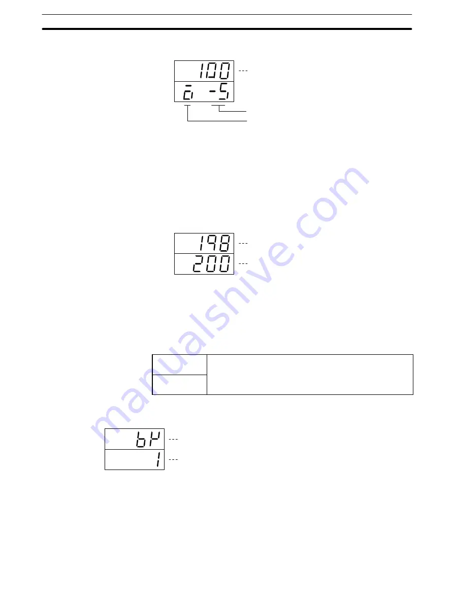
Manual Output Volume (Display Level 0)
PV
SV
Process value (monitored every 100 ms)
Manual output volume of currently selected loop (Unit: %)
Parameter signal of manual output volume
Settings
•
This is used to manually manipulate the output volume. It is valid when the out-
put relay “MAN” bit is ON.
•
The “MAN” bit can be turned ON and OFF by means of a device such as the
Programming Console, or by means of the user program. For details, refer to
Section 4 PC Memory Allocation and Programming.
PV and SV (Display Level 0)
PV
SV
Process value (monitored every 100 ms)
Set point of currently selected bank and loop (unit:EU)
Valid SV Range
Set the set point in the range between the scaling lower limit and the scaling up-
per limit.
Error Display
When a sensor error occurs, one of the codes below and the detected tempera-
ture blink alternately in the PV display.
ser1
The analog input is out of the range: (input measurement range +
10%FS). That is, 10%FS below the lower limit or 10%FS above
the upper limit Includes broken or incorrect input wiring
ser2
the upper limit. Includes broken or incorrect input wiring.
ser1
: Loop1 or Loop1 and Loop2 simultaneously.
ser2
: Loop2
Bank Number (Display Level 0)
PV
SV
Bank number parameter symbol
Currently set bank number.
During control operation: Executed bank number
Control operation interrupted: Currently displayed bank number
Settings
•
The bank number can be changed.
•
The changed SV is reflected in the bank number display (BK).
Bank Number and Executed Bank Number
The executed bank number cannot be changed from the Data Setting Console.
When changing these parameters from the Data Setting Console, stop opera-
tion. While operation is stopped, the bank number setting can be changed.
Parameter Displays and Settings


