2
OMRON Scientific Technologies Inc.
© OMRON STI 0613 PN99804-0060 Rev. B
8
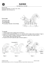
Figure 2-2 System Components
Table 2-1 System Components Identification
Chart #
Chart #
1
RECEIVER
7
TRANSMITTER
2
Individual Beam Indicators (one for each beam) - Red
8
Detection Zone
3
Blanking Active - Amber
9
Flip door. Access to configuration switches (on both
receiver & transmitter)
4
INTERLOCK or ALARM Indicator - Yellow
10
Status Indicator - Yellow
5
MACHINE RUN/STOP Indicator - Green/Red
11
Side Mounting T-Slot
6
RECEIVER CONNECTIONS M-12 (Male)
12
TRANSMITTER CONNECTIONS M-12 (Male)
F
+24 VDC - Blue Wire
M
+24 VDC - Blue Wire
D
0 VDC - White Wire
N
0 VDC - White Wire
C
OSSD 1 - Black Wire
L
Earth - Green Wire
J
OSSD 2 - Brown Wire
E
Earth - Green Wire
RECEIVER
TRANSMITTER
DETECTION
ZONE
TRANSMITTER
LED INDICATOR
ALTERNATE
T-SLOT
MOUNTING
RECEIVER LED
INDICATORS
E
F
C
D
1
2
3
4
5
6
7
8
9
10
11
12
J
L
M
N
Buy: www.ValinOnline.com | Phone 844-385-3099 | Email: [email protected]