. . . . .
OMRON SCIENTIFIC TECHNOLOGIES INC.
Fremont CA USA
Tel: 1/888/510-4357 in USA and Canada
© OSTI 1209 PN99584-0050 Rev. E
Original Instructions
43
10.2.3
C
ONNECTING
S
OLID
S
TATE
S
AFETY
O
UTPUTS
TO
T
WO
F
ORCE
-G
UIDED
R
ELAYS
See
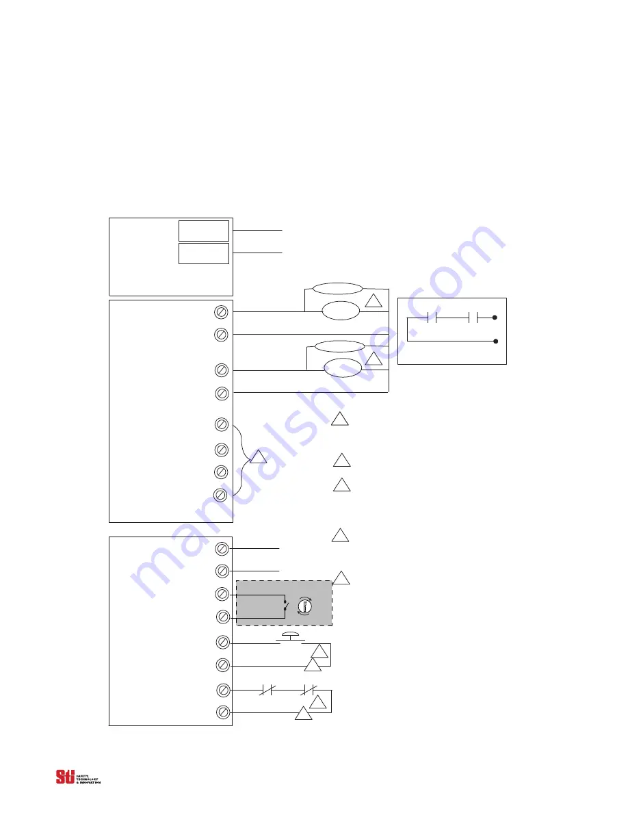
for preferred connection diagram when connecting via Two FGR (force guided)
relays. The FGR relays provide force-guided contacts for the machine control circuit.
TB1
Terminals on Main Board
+24 VDC
0 VDC
TB4
OSSD 1
Preferred Connection Diagram when Connecting Via Two Force-Guided Relays
MPCE 1
MPCE 2
TVS
TVS
Notes:
Suppression devices should be installed across
the coils of the machine control relays.
Two diode type devices are supplied in the
documentation kit.
No external power is to be applied to terminals
on TB 7 and TB8.
The relay contacts on the MPCE1and MPCE2
must be force-guided contacts. To activate
this function pos. 3 on SWA & SWB must be active.
A jumper is needed when MPCE is inactive.
See figure 3-5, item 14 and 16.
A N. C. or N. O. Remote Start input is selectable,
a momentary N. O contact is shown. The selection
jumper, Jumper 1, is located on the User control board.
See figure 3-5, Item 19.
24VDC Supply Voltage
Machine control contacts
MPCE 1
MPCE 2
1
2
3
4
1
1
5
OSSD 2
Return
Return
NPN Aux. 1
Aux. +24V
PNP Aux. 2
Return
5
Aux. Outputs may also connect to PLC.
TB7
Terminals on Main Board
1
START
MPCE 1
MPCE 1
2
2
3
4
2
MPCE
1
2
1
2
Program
Sel 1
Sel 2
Must be accessible only by key.
MCS
Figure 10-6 Connecting with Two Force Guided Relay Outputs


