background image

Connector

Description

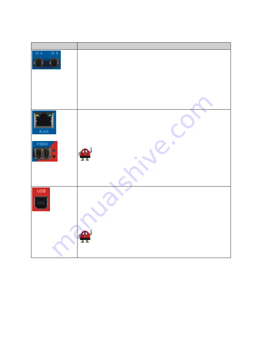
Optical output 4 and 5 (ST connector, 820 nm).

Outputs 4 and 5 can be configured in the Web Interface for the following
signals:
- IRIG-B unmodulated
- PPX (adjustable number of pulses, for example, 1 PPS or 1 kHz)
- DCF77 unmodulated
- Trigger (1 pulse at a defined point in time)
- Trigger (PPX sequence starting at the defined point in time)

For information about configuring these outputs, please refer to section
"Output configuration page" of the TICRO 100 User Manual.

RJ45

: 10/100Base-TX twisted-pair Ethernet port (RJ45 socket).

FIBER

: 100Base-FX optical fiber Ethernet port (ST connector, 820 nm).

The LEDs indicate the link status and data traffic.

TICRO 100

 can use only one Ethernet port at a time.

If no Ethernet port is selected in the Web Interface, the RJ45
Ethernet port is the default port if 

TICRO 100

 does not detect an

operating Ethernet network on any of the network ports during the
first power-up or after a factory reset. It is strongly recommended to
set the network port in the Web Interface manually during
commissioning (see section "Network configuration page" in the
TICRO 100 User Manual).

USB port (USB 2.0, type B). Use this interface as an alternative for
connecting a computer to 

TICRO 100

 (instead of accessing 

TICRO 100

 via

Ethernet).

Access via the USB port can be disabled in the security configuration (see

Access Restrictions

 tab in section "Security configuration page" of the

TICRO 100 User Manual).

When accessing the 

TICRO 100

 Web Interface via the USB port,

you should take care that the computer is 

not

 connected to the

Ethernet network 

TICRO 100

 is connected to. The computer must

not be connected to 

TICRO 100

 over the Ethernet network and the

USB port at the same time!

Device description

OMICRON

11

Содержание TICRO 100

Страница 1: ...Smart Measurement Solutions TICRO 100 Quick Start Guide...

Страница 2: ...without announcement OMICRON electronics is not to be held liable for statements and declarations given in this quick start guide The user is responsible for every application described in this quick...

Страница 3: ...N rail mounting 14 3 2 Wall mounting 15 4 Power supply 16 4 1 Power supply via Power over Ethernet 16 4 2 Power supply via the delivered plug in power supply unit 17 4 3 Power supply via an external D...

Страница 4: ...erence at his own expense Changes or modifications not expressly approved by the party responsible for compliance could void the user s authority to operate the equipment Declaration of Compliance Can...

Страница 5: ...this Quick Start Guide TICRO 100 is exclusively intended for the applications specified in chapter Introduction and designated use of the TICRO 100 User Manual The manufacturer or the distributors ar...

Страница 6: ...start measurements at different locations at exactly the same time Generation and distribution of 10 MHz reference frequency signals over Ethernet TICRO 100 provides a highly accurate 10 MHz referenc...

Страница 7: ...active Ethernet port Status LEDs and output status LEDs Reset pushbutton DIN rail clip Type plate with serial number on bottom side Mounting wholes for wall mounting brackets covered by sealing plug...

Страница 8: ...ff Device is in recovery mode waiting for new software In the recovery mode the device provides only a rudimentary Web Interface just allowing for the upload of a software image off blinking Software...

Страница 9: ...CRO 100 was in the Locked state before it enters the Hold over state if synchronization to the PTP time signal gets lost If configured in the output configuration TICRO 100 continues to output time si...

Страница 10: ...PPX TTL signal adjustable number of pulses for example 1 PPS or 1 kHz DCF77 unmodulated TTL signal Trigger TTL signal 1 pulse at a defined point in time Trigger TTL signal PPX sequence starting at the...

Страница 11: ...Ethernet port is the default port if TICRO 100 does not detect an operating Ethernet network on any of the network ports during the first power up or after a factory reset It is strongly recommended...

Страница 12: ...6 WARNING Death or severe injury caused by high voltages possible Use a power supply unit that complies with the SELV standard if product safety according to IEC 61010 1 and IEC 60255 27 is required T...

Страница 13: ...s a second DC source in addition to this DC power input to provide power supply redundancy for TICRO 100 For more details please refer to chapter Power supply on page 16 WARNING Death or severe injury...

Страница 14: ...o TICRO 100 TX10 screwdriver required Do not use other screws than delivered with the DIN rail clip 3 Hook the spring side of the DIN rail clip to the top side of the DIN rail 4 Press the device downw...

Страница 15: ...ve two sealing plugs on the rear side and two sealing plugs on the front side of TICRO 100 2 Unscrew the four uncovered screws from TICRO 100 3 Insert the four sealing rings included in the mounting k...

Страница 16: ...wer inputs make sure to observe the correct polarity for both inputs Reversed polarity on one of the DC power inputs would make the reverse polarity protection ineffective and could damage TICRO 100 I...

Страница 17: ...d 4 3 Power supply via an external DC supply voltage TICRO 100 can also be supplied by an external DC supply voltage using the DC power input socket on the front side A corresponding two pin connector...

Страница 18: ...nly USB 2 0 port available While accessing TICRO 100 via USB the computer must not be connected to the same Ethernet network TICRO 100 is connected to If you are accessing TICRO 100 from a Mac or Linu...

Страница 19: ...ly configured to obtain the IP address automatically However it is also possible to assign a static IP address to TICRO 100 In this case the following behavior applies When accessing TICRO 100 via Eth...

Страница 20: ...n dialog is displayed Enter your password and click Login The default password is timeterminal 9 The start page of the TICRO 100 Web Interface is displayed You can now access all pages of the Web Inte...

Страница 21: ...1 Troubleshooting procedures Problem LED Indication Description Possible Cause Remedy Green LED S1 is on Red LED S2 is off TICRO 100 is ready for operation LEDs S1 and S2 are continuously off TICRO 1...

Страница 22: ...air copper line or FIBER for 100Base FX optical fiber If the currently active Ethernet port is not the port actually used change the network interface configuration in the TICRO 100 Web Interface Disc...

Страница 23: ...Resetting the device to the factory defaults may be necessary if you forgot your password or if you cannot access the TICRO 100 Web Interface anymore because you selected the wrong Ethernet network po...

Страница 24: ...t is one of our top priorities At our technical support hotline you can reach well educated technicians for all of your questions Around the clock competent and free of charge Make use of our 24 7 int...

Страница 25: ...Version 2 0 info omicron lab com www omicron lab com OMICRON Lab 2018 TICRO 100 Quick Start Guide engl All rights reserved...

Отзывы: