Page
Page
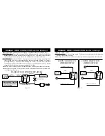
ALARM BROWN
WIRE to pin 86
-6
-7
BROWN WIRE: (siren 12 volt 1amp positive output). FUNCTION ONE: To provide a
constant 12 volt, 1 amp positive output directly to the electronic siren supplied in this
package. FUNCTION TWO: To provide a constant 12 volt, 1 amp positive output
directly to an optional relay coil, to allow additional devices (car horn, air horns, sirens
or pagers) to come on when alarm is sounding. CONNECTION ONE: Connect alarm
brown wire directly to electronic siren red positive wire. Only when alarm is triggered
“on”, or arm/disarm chirp confirmation, will the brown wire have 12 volts output to
siren. NOTE: If brown wire touches ground directly without a load it damages circuit.
BROWN WIRE CONNECTION siren + wire
GREEN WIRE CONNECTION negative door trigger
30
Relay
86
87
87A
85
C
O
I
L
30
Relay
86
87
87A
85
C
O
I
L
ALARM
SIREN
SIREN RED WIRE
ALARM
BRAIN
12345
12345
12345
12345
DOME LIGHT
DOOR PIN SWITCH
ALARM BROWN
WIRE to pin 86
ALARM GREEN WIRE CONNECTION TO DOOR
TO +12 V
CAR
HORNS
ALARM BRAIN
+
TO +12 V
+
+FUSE BOX
+
OPTIONAL CONNECTION TWO:
Connect alarm brown wire to the positive
side of optional relay coil pin 86. Connect
relay coil pin 85 to ground. Only when alarm
is triggered “on” or arm/disarm confirma-
tion chirps will brown wire work relay coil.
NOTE: If brown wire touches ground directly
(without a one amp load) it can damage
alarm circuit.
NOTE: Do not connect alarm brown wire to the
siren and relay output at the same time. If one
or two relays are used then connect siren red
positive wire to relay contact pin 87.
Flasher
GREEN WIRE: (Door negative instant trigger wire with G.M. de-bounce circuit).
FUNCTION ONE: If the green wire becomes grounded after alarm has armed, the alarm
will trigger . If the green wire is grounded at the time alarm becomes armed from the
transmitter, the circuit by-pass feature will leave the green wire circuit unprotected until
the circuit becomes ungrounded. FUNCTION TWO: For last door arming to work. After
the ignition switch is turned "off", the exit delay countdown will not begin until the green
wire changes from being grounded to ungrounded. (Example: any door opened, then the
last door closes). Note: If any door on this circuit is re-opened within the 30 second exit
countdown, the countdown will stop for as long as the door is open. Once the last door
closes, the countdown resets and 30 seconds later the alarm automatically arms itself.
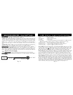
FUNCTION THREE: When the alarm is triggered by the green wire the L.E.D. light will
start flashing (3 times & pause) until the ignition switch is turned “on”.
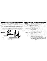
CONNECTION: If factory dome light pin switches are the grounding type, connect the
green wire to a wire which is common to all the door pin switches. Note: If the car has
a delay dome light the circuit by-pass feature will allow alarm to be armed from the trans-
mitter instantly and will start protecting the green wire circuit when the dome light turns
off. In passive arming mode, the alarm arms 30 seconds after the dome light turn off.
Test the target wire for ground when any of the doors are opened.
NEGATIVE COURTESY LAMP SYSTEM:


