Page
Page
ff
-12
-13
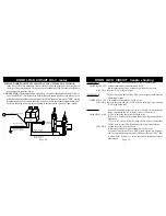
ORANGE WIRE: (500ma Negative Output For Optional Starter Interrupt Relay).
FUNCTION ONE: To provide a constant 500ma ground output for a relay coil only when
alarm hijack is activated, alarm is armed or triggered “on”. This allows relay to disable
the starter only when starting vehicle for minimum current draw on battery.
CONNECTION: For Starter Disable: Connect orange wire to the negative side of optional
relay coil pin #86. The wire from ignition key to starter solenoid will read 12 volts only
when ignition key is in start position (cranking the vehicle). Cut this wire at a suitable
location. Ignition key side of this cut wire, connect to pin #85 and #30 of relay. Starter
solenoid side of this cut wire connect to pin #87a of relay.
Note: Only while cranking vehicle will a small drain be on battery from the use of this relay.
Note: If this wire touches 12 volts positive directly or has more than a 500ma ground load,
it will damage this circuit.
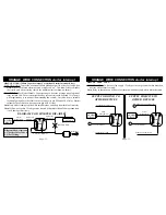
ORANGE WIRE CONNECTION starter interrupt
ORANGE WIRE CONNECTION starter interrupt
ORANGE WIRE CON'T:
FUNCTION TWO: To have a relay supply 12 volts positive or ground to other detection
devices when alarm is armed.
Note: Relay in function two will have current draw on battery only while alarm is armed.
30
Relay
86
87
85
C
O
I
L
87A
ALARM
BRAIN
To 12 Volts Positive
30
Relay
86
87
85
C
O
I
L
87A
ALARM
BRAIN
To 12 Volts Positive
SUPPLY GROUND TO
OTHER DEVICES
SUPPLY POSITIVE TO
OTHER DEVICES
Connect To Ground
Connect To Other Device
30
Relay
86
87
85
C
O
I
L
Starter Motor
SOLENOID
87A
ALARM
BRAIN
Ignition Key
DIAGRAM FOR STARTER DIS-ABLE
AU-Socket
White Wire
AU-Socket Red Wire
Cut Starter Wire
Connect To Other Device
Connect To 12 Volts Positive
+
+
+
Diagram Shows Optional
AU-Socket Color Code &
AU-Pot Wiring.
Alarm
Orange Wire
Alarm
Orange Wire
Alarm
Orange Wire
AU-Socket
Orange Wire


