AUTHOR Alarm IGLA, Service Manual
Introducing the AUTHOR Alarm IGLA – a revolutionary product designed to provide the ultimate security. Our comprehensive Service Manual is available for free download, ensuring you have all the necessary information at your fingertips. Get your user manual from manualshive.com and unlock the full potential of this cutting-edge alarm system.
Share
Download


Reviews:
No comments
Related manuals for IGLA
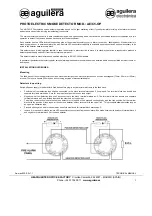
AE/C5-OP
Brand: aguilera electronica Pages: 2

RDW-75
Brand: Pure Acoustics Pages: 10

VS2100XR
Brand: Uniden Pages: 12

VS2000XR
Brand: Uniden Pages: 8

SA2
Brand: Draper Pages: 8

SA1
Brand: Draper Pages: 8

MUSICAL WAKE UP
Brand: Chicco Pages: 32

FireSafe
Brand: Konyks Pages: 8

SF804
Brand: EVERSPRING Pages: 13

BAJK
Brand: IKEA Pages: 8

1369245
Brand: BASETech Pages: 12

EDA-R5000 Zerio plus
Brand: Electro Detectors Pages: 3

EFW 6000
Brand: Eurochron Pages: 8

EFW 9000
Brand: Eurochron Pages: 8

CR-680BT
Brand: Guanxing Photoelectric Products Pages: 9

CLK-210
Brand: Steren Pages: 3

BEDDI
Brand: Witti Pages: 8

EN1104
Brand: Clas Ohlson Pages: 16


