

Ae-man-320-0.0 v1.1
TECHNICAL MANUAL
HEADQUARTER OFFICE & FACTORY
: C/ Julián Camarillo, 26 28037 – MADRID (SPAIN)
Phone.:+34 91 754 55 11
www.aguilera.es
1
PHOTOELECTRIC SMOKE DETECTOR MOD.: AE/C5-OP
The AE/C5-OP
Photoelectric smoke detector operates based on the light scattering effect (Tyndall principle) providing a fast alarm activation
particularly in case of slow-burning (smouldering) fires occurs.
The main detector component is a dark chamber equiped with a light-emitting diode cell faced to a photodiode receptor set capables by a join
operation to detect if any smoke particles have entry into the dark chamber.
Each detector has two LEDs located in oppositive side at the external assembly cover to inform to users by flashing about if the detector is in
stand-by operation or in permanent alarm as well. Remote LED annunciator capability is available upon request as an optional accessory to be
wired to the detector base terminals block.
This detector have a latching alarm feature. In case the detector in alarm function to move it to stand-by operation is requested to produce a
detector power supply switch-off from the remote fire alarm panel.
This detector model is manufactured and certified according to EN 54-7:2000 standard.
In general all photoelectric detector types for smoke alarm applications are recommended to be installed within no dust polluted ambient rooms or
inner zones.
INSTALLATION GUIDELINES.
Mounting
The fixed base of the smoke detector should be mounted directly onto an electrical junction box such as an octagonal (75mm, 90mm or 100mm),
a round (75mm) or a square (100mm) box without using any type of mechanical adapter.
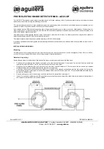
Detectors loop wiring
Switch-off power supply to the detector´s fixed base before plug-in any detector main frame to the fixed base.
Positive wire from detection loop shall be connected to the block terminal marked as 2 (loop input). The terminal block has double and
separate terminals marked as 2, one for loop input and the other one as loop output.
Negative wire from detection loop shall be connected to the block terminal marked as 5. The terminal block has double and separate
terminals marked as 5, one for loop input and the other one as loop output.
To built-up the detection loop to the next one detector or to the end of line proceed connecting by wire the free position 2 at the terminal
block with the position 2 (loop input) at the next one detector´s block terminal or to the end of line . This procedure allows detection loop as
an open line operation type.
Proceed with negative wire in the same way as before mentioned for terminal block marked as 5.
In case it is required to install a remote LED annunciator, connections from annunciator will be made between its positive to terminal block 6
and negative to terminal block 3 at the base detector.