background image

OMAX JetMachining® Center Operator’s Guide

Maintenance

4 - 16

400433D-EN


Mixing Chamber Disc and Orifice Assembly

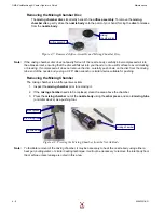
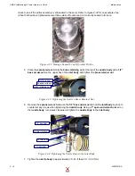
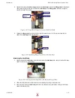
1.

Install an 

O-ring

 onto the 

nozzle body

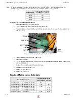
Figure 4-26: Installing the O-ring on the Nozzle Body

Caution:

Ensure that the nozzle body, the mixing chamber disc, and the mixing chamber surfaces are 
clean and contamination free. 

2.

Assemble the 

mixing chamber disc

 and 

orifice assembly

 inside the 

nozzle body

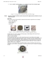
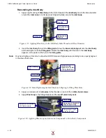
a.

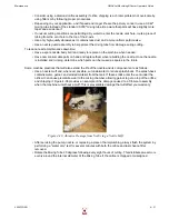
Place the 

mixing chamber disc

 on the 

mixing chamber

 in the center bore of the 

nozzle 

body

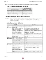
Figure 4-27: Placing the Mixing Chamber Disc in the Center Bore of the Nozzle Body

b.

Ensure that the 

mixing chamber disc

 sits flat on the 

mixing chamber

, leaving a 0.030" (0.76 

mm) deep bore to accommodate insertion of the 

orifice assembly

.

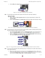
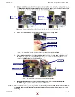
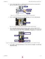
c.

Insert the 

orifice assembly

 with the jewel side facing up into the 

nozzle body bore

 and on 

top of the 

mixing chamber disc

.

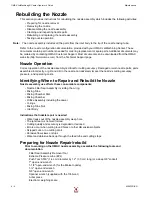
Figure 4-28: Inserting the Orifice Assembly in the Nozzle Body with the Jewel Side Facing Up

Note:

Ensure that the orifice assembly is well-seated in the 0.030" 

(0.76 mm) 

counter bore above the mixing 

chamber disc. Ensure that no contamination exists between the orifice assembly and the mixing chamber 
disc as this will impact jet stream alignment.

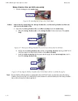
o-ring installed 
on nozzle body

mixing chamber 
disc

nozzle body

orifice 
assembly

nozzle body

Содержание JetMachining Center 2626

Страница 1: ...JetMachining Center Operator s Guide OMAX Corporation Information 253 872 2300 21409 72nd Avenue South Fax 253 872 6190 Kent WA USA 98032 Technical Support 800 298 4036 Web http www omax com E mail omax omax com ...

Страница 2: ...umentation If you have any questions or concerns about the content of this operator s guide we want to hear from you Please email us at tech_writing omax com or contact us by mail at OMAX Corporation Technical Publications 21409 72nd Avenue South Kent WA USA 98032 OMAX Corporation is continually improving the OMAX JetMachining System to bring you the best in abrasivejet machining technology For th...

Страница 3: ...al in ensuring safe equipment operation Explains the safety devices built into the OMAX equipment Safety checklist form Chapter 2 Introduction Identifies the major components of the JetMachining Center and breaks each down into their individual pieces providing names and descriptions Shows the location and explains operator control devices Lists accessories currently available for your JetMachinin...

Страница 4: ...uipment operation Contains maintenance information for the pump dump valve Chapter 5 Customer Support Provides OMAX customer support contact information Explains how to order and return parts for your JetMachining Center Chapter 6 OMAX Glossary Definitions of terms specific to OMAX and the waterjet industry ...

Страница 5: ...the JetMachining Centers 2 7 PC Controller 2 8 Control Panel Switches 2 9 X Y Table 2 9 Accessories for the OMAX JetMachining Center 2 10 Tilt A Jet 2 10 Precision Optical Locator 2 11 Waterjet Brick 2 11 MaxJet 5 MiniJet Nozzle 2 11 Solids Removal System 2 12 Chiller 2 12 Drill Head Attachment 2 13 Closed Loop Water Recycling System 2 13 Terrain Follower 2 14 Chapter 3 Operation Operating the Hig...

Страница 6: ...dy 4 6 Removing the Filter Seal Assembly from the Inlet Body 4 7 Removing the Orifice Assembly 4 7 Removing the Mixing Chamber Disc 4 8 Removing the Mixing Chamber 4 8 Removing the Nozzle Body O Ring 4 9 Cleaning and Inspecting Nozzle Components 4 9 Reassembling the Nozzle Assembly 4 14 Nozzle Filter Seal Assembly 4 14 Mixing Chamber 4 15 Mixing Chamber Disc and Orifice Assembly 4 16 Nozzle Body 4...

Страница 7: ...Keypad Display 4 47 Troubleshooting the OMAX JetMachining Center 4 48 Machine Motion 4 48 Machining Quality 4 48 Software Problems 4 52 Nozzle and Abrasive System 4 53 Miscellaneous 4 54 Positioning Accuracy Overview 4 55 Consumable Parts 4 57 Maintenance Log 4 59 Training Log 4 60 Chapter 5 Customer Support Contacting OMAX Customer Service 5 1 Ordering Parts 5 1 Returning Parts 5 1 Returned Mater...

Страница 8: ...OMAX JetMachining Center Operator s Guide viii 400433D EN ...

Страница 9: ...ter Recycling System 2 13 Figure 2 21 OMAX Terrain Follower Attached to a Tilt A Jet 2 14 Figure 3 1 The Abrasivejet Nozzle 3 4 Figure 3 2 The Abrasive Waterjet System 3 5 Figure 3 3 Quality Examples 3 6 Figure 3 4 Using Tabs Prevents Small Parts from Falling in the Tank 3 7 Figure 3 5 Cutting Nozzle with a Muff Attached 3 8 Figure 3 6 Selecting Auto Home in OMAX Make 3 11 Figure 3 7 White Water T...

Страница 10: ...fice 4 18 Figure 4 33 Tightening the Nozzle s Brass Retainer Nut 4 18 Figure 4 34 Tightening the Nozzle Body to the Inlet Body 4 18 Figure 4 35 Inserting the Mixing Tube into the Nozzle Body 4 19 Figure 4 36 Placing the Mixing Tube Collet and Nut onto the Mixing Tube 4 19 Figure 4 37 Tightening the Mixing Tube onto the Nozzle Body 4 19 Figure 4 38 Abrasive Damage from Not Using a Nozzle Muff 4 21 ...

Страница 11: ... 4 76 Select the ORD file Variable Dump Orifice Adjustment Routine 4 36 Figure 4 77 Click the Nozzle Test Button to Set Pump Pressure 4 37 Figure 4 78 The Test Pump and Nozzle Window 4 37 Figure 4 79 Set the KSI for WaterPres on the Pump s LCD 4 38 Figure 4 80 Click the Test STOP Button After Setting Your Desired Pump Pressure 4 38 Figure 4 81 Click Start to Pressurize the Adjustable Dump Orifice ...

Страница 12: ...OMAX JetMachining Center Operator s Guide xii 400433D EN ...

Страница 13: ...edges Electrical Hazard Indicates the presence of life threatening voltages Never access areas labeled as such without first taking appropriate safety precautions locking out power verifying no voltage present on circuits prior to maintenance activities etc Lock Out Power Never open or do maintenance on the OMAX equipment with the main AC disconnect ON or unlocked or while the pump unit is operati...

Страница 14: ...r step stand or walk on the support slats They are weakened with continued cutting and may collapse under your weight Never place your hands or fingers in areas where they are in danger of becoming pinched during equipment operation Never operate the equipment with the protective covers missing exposing yourself to dangerous mechanical and electrical hazards Removing the abrasive feed hose from th...

Страница 15: ...irst OMAX JetMachining Center Operator s Guide 400433D EN 1 3 Placement of Safety Labels Figure 1 1 Safety Labels for the OMAX Models 2626 2626 xp 2652 5555 and 55100 Figure 1 2 Safety Labels for the OMAX 80160 ...

Страница 16: ...OMAX JetMachining Center Operator s Guide Safety First 1 4 400433D EN Figure 1 3 Safety Labels for the OMAX 60120 Figure 1 4 Safety Labels for the OMAX 80X ...

Страница 17: ... Treat all injuries with caution Because bacteria in the water can build up even a seemingly minor break in the skin can introduce harmful bacteria into the wound Any injury involving contact with the water should receive immediate attention Use antibacterial chemicals in the tank water exception is with EBBCO Closed Loop to reduce this hazard and always wear protective gloves if you have cuts or ...

Страница 18: ...n t switch tank chemicals for bacterial control without first reading the manufacturing warnings on the labels Mixing different chemicals can create a hazardous situation Don t use silica sand as a cutting abrasive Fine silica dust produced by the cutting process can lead to silicosis a serious lung disease Don t operate the machine in close proximity to other machines or electrical equipment as w...

Страница 19: ...ottom with sufficient force to cut through it Figure 1 6 Sound Level Map of OMAX JetMachining Center PUMP CONTROL TABLE OPERATOR STATION USINGdBMETER REALISTICSET AT80 RANGE WITHSLOWRESPONSEAND A FILTERSETTING CUTTING1 2 A LUMINUM PLATE FULLYSUBMERGED AMBIENTNOISE WITHNOCU TTING 66dB 18 FROM CUTTING HEAD FOR THISTEST AVG82dB 85 86dBPEAK CUTTING ZONE 78dB 78dB 79dB 6ft 1 8m 3ft 9m 9ft 2 7m 9ft 2 7m...

Страница 20: ...ssure has exceeded the factory set pressure limit it stops the pump and displays Dead head of Pump on the pump display panel 3 Electrical Protection The variable frequency drive VFD provides electrical protection as well as speed control for the pump s main drive motor A circuit breaker provides short circuit protection for the charge pump motor Circuit breakers protect the internal transformer an...

Страница 21: ...emove power from equipment when not in use Operate equipment after reading equipment manuals and receiving qualified instruction Be able to quickly access the emergency stop switch Start pump only when all side panels are in place Maintain protective guards and shutdown devices on around pump Immediately notify repair personnel if leaks are found in pump fittings or connections Follow manufacturer...

Страница 22: ...OMAX JetMachining Center Operator s Guide Safety First 1 10 400433D EN ...

Страница 23: ...aracteristics produces surge free starting and provides high power factors and VFD motor efficiencies throughout the useful power range Pump components are mounted in a compact enclosure that occupies only 15 square feet 1 4 square meters of floor space All electrical control components and the VFD are located in the electrical enclosure mounted on the end of the pump unit Figure 2 8 The main elec...

Страница 24: ... and the pump s start stop controls When the pump is attached to an OMAX JetMachining Center control is shared between the JetMachining Center Controller and the pump keypad Figure 2 3 Pump Control Panel Components electrical disconnect optional lockable door latch air intake filter charge pump switch emergency stop switch power switch pump control panel keypad and display front panel removal scre...

Страница 25: ... is lit when the pump is in run mode Stop Button Stops pump operation whenever pressed When held down for 3 seconds displays the pump s operational mode model number and software version The red status light to the right of this button is lit when the pump is stopped Reset Button Press the reset button to clear a pump fault condition Pressing either the up or down arrow while also pressing the Res...

Страница 26: ...emergency stop switch is disengaged reset by manually pulling it back to its original position The pump and JetMachining Center cannot be restarted until the emergency stop switch is reset Note Pushing the emergency stop switch in either the emergency stop switch on the pump or the emergency stop switch on the JetMachining Center immediately shuts down both the pump and the JetMachining Center If ...

Страница 27: ...iew With Front Panel Removed Figure 2 6 Pump with Top Lid Open and Front Panel Removed top lid front panel controls white water tank AC power cable water filters x2 pump drive AC motor high pressure safety valve pump crankcase wet end assembly adjustable dump orifice charge pump ...

Страница 28: ...ure 2 8 Pump Internal Components on Right Side pump manifold wet end pump cylinders x3 belt cover guard hinged pump lid water pressure gauges x2 water filters x2 pump crankcase low pressure input water lines x3 high pressure safety valve cooling water lines x3 adjustable dump orifice variable frequency drive VFD air filter power distribution terminals ...

Страница 29: ...e On and Off and guides the abrasivejet on its precise tool path Refer to Figure 2 11 page 2 8 High pressure Water Pump The high pressure water pump pressurizes the water used by the OMAX abrasivejet nozzle Refer to Figure 2 2 page 2 2 X Y Table The X Y table moves the abrasivejet nozzle above a large catcher tank containing water from the cutting process and providing a settling tank for spent ab...

Страница 30: ...uter is accessible by lifting up the computer access panel The controller s hinged arm allows you to position the cabinet according to your viewing requirements The keyboard and mouse are water resistant for reliable operation in an abrasivejet environment Figure 2 11 The JetMachining Center PC Controller PC Controller garnet hopper Y axis Z axis X axis X Y table catch tank abrasivejet nozzle abra...

Страница 31: ...g cut Emergency Stop Immediately shuts down the water pump and abrasivejet operation The emergency stop E stop should be used only for real emergencies When pressed the OMAX loses important machine positioning information Caution The abrasive feed line must always be cleaned out after using the Emergency stop switch Pause Pauses motion and shuts down the abrasivejet nozzle Machining can be restart...

Страница 32: ...s The motors are brushless with positioning feedback Each command to the servo amplifier causes the carriage to move approximately 0 0005 0 01 mm Figure 2 13 The OMAX 80X JetMachining Center Accessories for the OMAX JetMachining Center A number of optional accessories are available for your OMAX JetMachining Center For current prices and ordering information contact your OMAX distributor For a com...

Страница 33: ...cator Waterjet Brick The waterjet brick replaces the normal tank slats to better support thin materials prevents small parts from falling into the tank and reduces back splash on materials being cut Figure 2 16 Waterjet Brick MaxJet 5 MiniJet Nozzle The MiniJet Nozzle provides a thin stream that produces a narrow precise cut with less taper than the standard MaxJet 5 nozzle The MiniJet easily swit...

Страница 34: ... kerf material from the tank reducing the downtime necessary for manual removal Figure 2 17 OMAX Solids Removal System Chiller High pressure pumps last longer when the inlet water temperature is always kept less than 70 F 21 C The Chiller maintains low water input temperatures preventing costly maintenance and equipment rebuilds Figure 2 18 OMAX Inlet Water Chiller ...

Страница 35: ...e control When the drill head attachment is activated pierces that are normally done with the jet can be done using a drill bit Figure 2 19 OMAX Drill Head Attachment Closed Loop Water Recycling System This closed loop system recycles waste water so that only a small amount of water is needed when operating the OMAX This reduces the load on the water drain system and also helps maintains water qua...

Страница 36: ...eping the nozzle at a constant distance above the surface of the material being cut The Terrain Follower can be retrofitted to any OMAX JetMachining Center having a motorized Z axis or Tilt A Jet It attaches directly to the machine s Z axis and uses a sensing foot that maintains contact with the surface of a material as it s being cut Changes in the material s height are detected and communicated ...

Страница 37: ...achining Center turns the high pressure pump ON to begin a cut and turns it OFF between cuttings Before starting the pump unit 1 Check the pump s maintenance log and other records for any ongoing service activities Verify that no Out of Service tags are posted on the pump s main electrical disconnect or on its On Off switch If service is scheduled and necessary have it completed before resuming pu...

Страница 38: ... pump stops verify that the red LED next to the keypad s Stop button is lit see Figure 2 4 4 Turn the charge pump switch to its OFF position 5 Turn the pump On Off switch to its OFF position Emergency Shutdown Procedures Pushing the emergency stop switch in immediately shuts down both the pump and the JetMachining Center The emergency stop switch is reset by manually pulling it back to its origina...

Страница 39: ...Hi PreSet value can be adjusted up to but not above the Operating Point output pressure value or a maximum of 2000 RPM Hi PreSet is the motor RPM value that the pump normally returns to when started When operated with the JetMachining Center it is the high pressure mode 5 Operating Point is the motor RPM corresponding to maximum performance and maximum horsepower available OMAX JetMachining Center...

Страница 40: ... eye protection when cutting Caution Do not operate the abrasive waterjet for more than several seconds when the nozzle is above the water surface at a distance greater than 1 5 inches 38 1 mm Air entrapment in the water increases with nozzle height eventually allowing the jet stream to strike the tank bottom with sufficient force to cut a hole through the bottom This applies to using Test Nozzle ...

Страница 41: ...e software prepares the Layout drawing for the cutting process It calculates the speed of the abrasivejet for optimum results and controls all machining operations Make can calculate how much time and abrasive material will be required to machine the part and allows you to review the exact path of the abrasivejet even when not connected to the OMAX JetMachining Center OMAX Interactive Reference Th...

Страница 42: ...the abrasivejet nozzle moves the slowest Quality also takes into account the material being cut When working with a softer material such as polypropylene for example a quality of 5 moves the abrasivejet nozzle much faster than a quality of 5 would while working with steel Quality is always relative to the machinability of the material Figure 3 3 shows how the surface finish changes with the qualit...

Страница 43: ...ill have more material to push upon Note The size of the high pressure water pump also affects the clamping required If the pump power is doubled the amount of force exerted on the material will also double WARNING Always use the proper lifting equipment when handling heavy materials Using Tabs for Holding Small Parts When cutting small parts design them using small holding tabs that prevent the p...

Страница 44: ...e noise level low during machining reduces splashing and spraying and protects the Z axis and cutting head components Always place a muff on the abrasivejet nozzle when machining This muff will eventually wear out Included with the OMAX software is a file called Muff in the SAMPLES USEFUL_TOOLS directory that contains the pattern needed for making additional muffs Use sponge material at least 1 2 ...

Страница 45: ...rasivejet is not cutting along a slat Cutting along a slat also shortens its life Rotate slats regularly Most parts are cut in the same area of the machine Slats located in this area tend to wear out first Rotating slat placement distributes their wear and extends their usefulness Orient the short direction of a part parallel to slats Try to arrange drawings so that the shortest dimension runs par...

Страница 46: ... motion of the abrasivejet nozzle This surface may be used for any special fixturing installed Note For additional tips on effective cutting consult the OMAX Interactive Reference where an entire section is devoted to tips Setting Soft Limits In the OMAX there are two types of limits that restrict the area of nozzle movement on a table s cutting surface absolute limits hard designed into the machi...

Страница 47: ...ately aligned and ready for use Operating the JetMachining Center Note The following guidelines for operating the JetMachining Center assume that the OMAX operator has received the factory training provided as part of the original equipment purchase and installation Configuring Your Drawing 1 Import your part file dxf into Layout the OMAX drawing tool 2 Use the Clean command to clean up the drawin...

Страница 48: ...pment 3 If installed close the bleed valves on the bulk hopper and common water air tank 4 Switch the air supply valve On 5 Switch the water supply valve On 6 Check the white water tank inside the pump Figure 3 7 to verify the water level is between one half and three fourths full 7 Power up the OMAX high pressure pump as follows a Turn the pump control panel switch On Verify pump operation by che...

Страница 49: ...perating system boots up without issues 9 When applicable also power ON any attached OMAX accessories solids removal system bulk feed hopper chiller etc 10 Verify the nozzle being used matches the size required for the part being cut Change it to the correct size when required Caution Changing the nozzle orifice size also requires adjustment of the dump orifice in the high pressure water line of t...

Страница 50: ...ed will be sufficient to finish cutting the part 13 Check the tank s water level Make sure that the material being cut can be covered and also uncovered with tank water Add or drain tank water as needed 14 In Windows click the OMAX Make icon to launch the cutting software 15 Auto Home the machine to ensure that the machine s zero absolute home position is set Figure 3 10 Caution Prior to auto homi...

Страница 51: ... out of water 18 Test nozzle operation at Low Pressure a Click the Test button to display the Test Pump and Nozzle options Figure 3 12 Pump and Nozzle Test Options b Select Low then click Water to begin the test Figure 3 12 c When the jet stream begins remove the abrasive feed tube from the abrasive feed block on the Bimba valve Figure 3 17 and block air flow through the feed tube by holding a fin...

Страница 52: ...n the quality of a nozzle s jet stream Figure 3 14 Comparison of Jet Streams with Different Jewel and Mixing Tube Conditions e Refer to Figure 3 15 to see how the shape of a jet stream s shape indicates the quality of its cutting performance Figure 3 15 Comparison Spread of Waterjets and Abrasive waterjets at Different Health States Good Orifice Badly Chipped Good Orifice Good Mixing Tube Chipped ...

Страница 53: ...When the jet stream begins pinch the abrasive feed tube until blocked to examine the quality of the jet stream verifying that it s straight and narrow as illustrated in Figure 3 13 Note Always plug the abrasive feed tube by pinching prior to visually inspecting the jet quality Air from the tube interferes with the jet stream making inspection difficult d During this jet stream test adjust the pump...

Страница 54: ...ner f Replace the abrasive feed block by pressing it back into the Bimba valve 22 Verify that the Pump Nozzle Settings in Setup match your actual measured values Caution It is critical that the software settings match your actual MEASURED values for the pump pressures and abrasive flow rate Also it is critical that the nozzle setup exactly match the nozzle installed on your machine If not properly...

Страница 55: ...hat those selections match your cutting requirements Click OK to save any changes made Configuring the Make Software 1 Select the drawing for your part a Click the Change Path Setup button or use File Open Change Path Setup from the menu bar and follow the path to where your drawing s file is stored b When located clicking the ord file name opens that drawing in the adjacent preview screen Note If...

Страница 56: ...als for Cutting on page 3 6 4 Position the nozzle to begin the cut and set the Path Start Home a Place the nozzle above the material being cut ensuring efficient use of the available material and where it will not overshoot the material during the cut b Once the nozzle is correctly positioned click Zero as the Distance from Path Start see Figure 3 23 Note This step may be omitted as the distance f...

Страница 57: ...arrow on the right side of the Z Height pop up display 9 Raise the water level in the tank above the cutting material 10 Begin cutting by clicking Begin Machining Begin Caution Always remain near the JetMachining Center during the cutting process In the event of a serious problem use the Emergency Stop switch to immediately halt operations 11 Once machining stops raise the nozzle lower the water l...

Страница 58: ...e OMAX Make and all other software applications running on the OMAX PC Controller 11 Click the Windows Start button and select Shut Down 12 Verify that the computer has powered down indicator lights off and a blank screen 13 If applicable depressurize the Bulk Feed Hopper 14 Turn the charge pump OFF 15 Switch the water supply valve OFF 16 Power the PC Controller OFF 17 Switch the air supply valve ...

Страница 59: ...TO HOMED to ensure that absolute home position is correct 11 Nozzle POSITIONED between slats 1 to 2 inches 2 54 5 1 cm above the water level 12 Nozzle low pressure water test STARTED Click Test Low and Water 13 Straight and narrow jet stream VERIFIED while pinching the abrasive feed tube 14 RPM and Pressure ADJUSTED and RECORDED from the pump LCD screen 15 Nozzle low pressure test STOPPED 16 Nozzl...

Страница 60: ... High and Water 3 Pump RUN for 20 seconds to clean and clear all abrasives then test stopped 4 Water LOWERED to lowest level 5 Nozzle POSITIONED at desired location for shut down 6 Floppy diskettes REMOVED from drive 7 Terrain Follower foot SECURED in up position 8 OMAX Make CLOSED 9 Windows Shut Down CLICKED 10 PC Controller POWERED OFF 11 PC shutdown VERIFIED no PC lights black monitor screen 12...

Страница 61: ...tant to change the crankcase oil according to the intervals specified in the maintenance schedule The oil must also be changed anytime it becomes contaminated with water or other debris Always use SAE 30 ISO 100 non detergent motor oil Use of other types of oil may shorten pump life If the temperature in the pump s physical environment exceeds 90 F 32 C use SAE 40 ISO 150 non detergent motor oil T...

Страница 62: ...l to drain 6 To force out remaining oil apply a small amount of shop air to the hole in the oil filler tube with the filler cap still in place 7 Replace the plug at the end of the red drain hose 8 Refill the oil through the filler pipe 9 Replace the filler pipe cap 10 Replace the front cover Routine Maintenance Schedule Pump Model Add additional quart of oil if RPM is less than P3050V 750 P3055V 8...

Страница 63: ...ly accumulate on the material being machined Inspect individual slats for wear replacing and rotating Inspect and rotate monthly Replace when excessively scored and no longer stable Clean the outlet water filter Check monthly Figure 4 13 Run tank cleaning program As needed when using the OMAX Solids Removal System SRS Add anti bacterial chemicals to the tank water controlling tank odor and bacteri...

Страница 64: ...or grit and dirt in the nozzle can adversely impact the nozzle s cutting accuracy pressure and operating costs Identifying When to Repair and Rebuild the Nozzle Nozzle assembly use affects these consumable components Nozzle Filter Seal Assembly including the o ring Mixing Tube Mixing Chamber Disc Mixing Chamber Orifice Assembly including the Jewel O rings Mixing Tube Nut Inlet Body Indications tha...

Страница 65: ...position convenient for nozzle assembly removal 4 Shut down the applications on the PC Controller by following proper shutdown procedures 5 Power Off the PC Controller 6 Power Off the OMAX pump 7 Switch Off the main AC power air and water sources to the machine Tag and lock them out according to established safety practices Follow all other company specified safety procedures Removing a MaxJet 5 N...

Страница 66: ...t from dropping while unscrewing it Figure 4 3 Removing the Nozzle Mixing Tube c Remove the mixing tube along with the locking nut and collet Carefully place all parts on your working area for later cleaning and inspection Caution The mixing tube even though it is made from abrasive resistant material will break if dropped or struck hard Removing the Nozzle Body from the Inlet Body 1 Place a 1 2 w...

Страница 67: ...to the Filter Seal 2 Pull the removal tool straight down to remove the filter seal assembly from the inlet body 3 Unscrew the removed filter seal assembly from the removal tool and discard it The filter seal assembly is a consumable item and will be replaced Removing the Orifice Assembly Carefully remove the orifice assembly from the nozzle body onto your working surface for later cleaning and ins...

Страница 68: ...on the disc from the mixing tube end of the nozzle body using a 3 16 Allen wrench or similar device suitable for pushing Removing the Mixing Chamber The mixing chamber is an infrequent wear item 1 Inspect the mixing chamber prior to removing it 2 If the mixing chamber needs to be replaced clean the area above the chamber 3 Press the mixing chamber out of the nozzle body using the arbor press and a...

Страница 69: ...les of garnet metal chips or small pieces of paper can negatively impact cutting 1 Make sure your work space is kept clean and free of contamination and your hands are clean prior to handling clean nozzle components In general you should wash all parts using a non abrasive mild soap with water or use an ultrasonic cleaner Note A small ultrasonic cleaner containing white vinegar is useful in cleani...

Страница 70: ...be extremely fine and not easily detected Orifice or Jewel Assembly The orifice assembly Figure 4 12 which contains the jewel is a consumable item that requires inspecting cleaning and replacing if damaged The hole in the jewel is very small approximately 0 014 0 36 mm in diameter for the MAXJET 5 orifice assembly and 0 010 0 254 mm in a MiniJet orifice assembly Water travelling through the orific...

Страница 71: ... high pressure system from entering the orifice A misaligned jet stream is one that cannot pass through the mixing tube without touching the inside bore when run at low pressure Garnet grit dirt or other contamination trapped between the orifice mount and the carbide disc or between the disc and the carbide mixing chamber can throw the jet out of alignment causing premature wear on the mixing tube...

Страница 72: ...e will wear away the inside of the mixing tube This results in a gradual irregular widening of the internal diameter of the mixing tube causing a less accurate stream of abrasive and water Figure 4 17 provides some examples of worn mixing tubes A cross section of these mixing tubes reveals the irregular wear of their internal diameter Figure 4 17 Worn Mixing Tubes The mixing tube is also very brit...

Страница 73: ...ork shut down the machine by following all required power shutdown and safety procedures 5 Remove the mixing tube from the abrasivejet nozzle turn it upside down and tighten it in the nozzle body 6 Start up the JetMachining Center 7 Again click the Test button and repeat the Water only test to try and dislodge the clogged material Figure 4 19 Installing the Mixing Tube Upside Down to Dislodge a Cl...

Страница 74: ...ticles or contamination using the nozzle test with the Water only Low pressure options see Figure 4 18 for test menu Repeat this test two or three times Figure 4 21 Purging the High pressure System of Contaminates with the Nozzle Removed Caution Make sure you maintain cleanliness throughout the nozzle reassembly and installation process Any contamination that gets into the nozzle components during...

Страница 75: ...ber 3 Screw the mixing tube retainer nut onto the nozzle body threads to prevent thread damage or place a 1 deep well socket over the 1 hex on the nozzle body for support Figure 4 25 4 Place the nozzle body in the arbor press and press the mixing chamber into the nozzle body bore using the 0 550 push tool and a 1 deep well socket Figure 4 25 Using the Push Tool and Arbor Press to Insert the Mixing...

Страница 76: ... the Center Bore of the Nozzle Body b Ensure that the mixing chamber disc sits flat on the mixing chamber leaving a 0 030 0 76 mm deep bore to accommodate insertion of the orifice assembly c Insert the orifice assembly with the jewel side facing up into the nozzle body bore and on top of the mixing chamber disc Figure 4 28 Inserting the Orifice Assembly in the Nozzle Body with the Jewel Side Facin...

Страница 77: ...d orifice assembly seated flat and centered in their correct positions Twist until you begin to feel resistance from the nozzle body and the nozzle inlet body Note The threads on the nozzle assembly of the Tilt A Jet are clocked to ensure that the abrasive inlet hole ends up in the proper position for attaching the abrasive hose Figure 4 31 Aligning the Nozzle s Abrasive Inlet Hole If the orifice ...

Страница 78: ... end wrench on the upper hex of the inlet body and tighten the brass retainer nut Figure 4 33 Tightening the Nozzle s Brass Retainer Nut 6 Remove the spanner wrench and use the 1 2 box end wrench to hold the inlet body in place to counteract any torque when tightening the nozzle body Using a 1 open end wrench placed on the nozzle body turn slowly clockwise to tighten the nozzle body to the inlet b...

Страница 79: ...collet and nut onto the mixing tube and insert the mixing tube all the way into the nozzle body until it bottoms out against the clean surface of the mixing chamber Figure 4 36 Placing the Mixing Tube Collet and Nut onto the Mixing Tube 3 While holding the mixing tube in place tighten the nut to a snug fit with an 11 16 open end wrench To counteract any torque place a 1 open end wrench on the hex ...

Страница 80: ...ings you can do to maximize the life of your nozzle components Don t change the Mixing Tube simply because the jet stream looks wide Cut test parts and do kerf checks on a regular basis to see when cutting performance begins to degrade If the surface quality and accuracy are as expected continue using the Nozzle Assembly If the quality of the cut part is not as expected prompt correction of the pr...

Страница 81: ...g the nozzle Once the nozzle is installed and running determine which parts can be reused as spares in the future Some machine practices that will also extend the life of the nozzle and its components are as follows Use a nozzle muff and whenever possible cut underwater to reduce splash back The splash back contains water garnet and eroded material from the tank If these solids enter the vent unde...

Страница 82: ...pulling on the air hose Figure 4 39 Removing the Air Hose from the Air Canister Fitting Ring 2 Use a 1 1 8 open end wrench to unscrew the on off valve air canister from the on off valve body Figure 4 40 Using a 1 1 8 open end Wrench to Remove the Air Canister 3 Use a 5 8 and a 3 4 open end wrench to carefully remove the coil nipple from the on off valve body adapter fitting Set this coil aside Fig...

Страница 83: ...ass retainer nut that holds the inlet body and place a 1 2 wrench on the upper hex of the inlet body holding it in place to counteract any torque while removing the inlet body from the tilting plate Figure 4 44 Removing the Inlet Body from the Tilting Plate 7 Use the spanner wrench to loosen the brass retainer nut while holding the inlet body The inlet body should detach from the machine at this t...

Страница 84: ...e a Stuck Inlet Body 2 Slide the tube over the threads on the tool post and thread the flange nut onto the tool post Figure 4 46 Placing the Tube over the Tool Post and Tightening the Flange Nut 3 Use the spanner wrench provided with your Tilt A Jet to remove the brass inlet body retaining nut Figure 4 47 Removing the Brass Inlet Body Retaining Nut with the Spanner Wrench body removal tool post in...

Страница 85: ...se a 1 5 8 open end wrench to detach the inlet body from the machine Figure 4 49 Tightening Flange Nut to Detach the Inlet Body Cleaning the Inlet Body 1 After removing the inlet body clean the hole where the inlet body sits using a brush with soapy water to remove any grit buildup Figure 4 50 Cleaning the Inlet Body Hole with Brush and Soapy Water 2 Rinse the hole with clean water and blow it com...

Страница 86: ...in the tilting plate Note Only hand tighten at this time to allow the On Off Valve and high pressure plumbing to be properly aligned in the steps that follow Figure 4 52 Hand Tightening the Inlet Body and Aligning to Tilting Plate Hole 3 Apply a small amount of anti seize to the threads on each of the 4 Allen head screws 4 Apply Blue Goop to the fitting threads and the on off valve body seat Figur...

Страница 87: ...7 Using a 5 mm Allen wrench and following a tightening pattern reinstall and tighten the four screws that secure the on off valve body to the tilting plate Tighten to turn at a time until all screws are tightened evenly Apply a coating of Blue Goop to the gland nut of coil nipple fitting Figure 4 56 Tightening the Four Valve Body Screws and Applying Blue Goop to the Gland Nut Threads 8 Using a 5 8...

Страница 88: ...Tilt A Jet are the same as removing a MaxJet 5 Nozzle Assembly with the exception of the additional steps required to remove the Inlet Body Extension the Dummy Orifice and the additional o rings and Ring Seals specific to the MiniJet Nozzle Note Only the additional steps required to remove the MiniJet 5 from the Tilt A Jet are presented here Refer to the steps presented in Removing a MaxJet 5 Nozz...

Страница 89: ...oving the MiniJet Nozzle Body from the Inlet Body Extension 2 With a 1 open end wrench placed on the nozzle body loosen the right hand threaded nozzle body from the inlet body extension using both wrenches Figure 4 59 and unscrew the nozzle body the rest of the way by hand Step 3 Remove the Inlet Body Extension from the Inlet Body 1 Place a 1 2 wrench on the inlet body located at the top of the no...

Страница 90: ...ove the MiniJet Dummy Orifice from the Inlet Body The MiniJet 5 also has a dummy orifice that sits at the top of the inlet body extension and needs to be removed This dummy orifice provides a flat surface for the inlet body seals 1 Remove the dummy orifice by tipping the Inlet body extension upsidedown and letting it fall out Figure 4 62 Inspecting the Dummy Orifice for Erosion Marks 2 Inspect the...

Страница 91: ...of these ring seals 2 Insert the ring seal assemblies into each end of the inlet body extension Figure 4 64 Installing Ring Seals and O rings in the Inlet Body Extension 3 Place the large o ring on the bottom of the inlet body extension Figure 4 64 4 Insert the dummy orifice inside the top of the Inlet body extension ensuring that it sits flat against the ring seal Figure 4 65 Inserting the Dummy ...

Страница 92: ...Nm 10 In the MiniJet nozzle body ensure that the orifice assembly and mixing chamber disc are properly installed and can seat as required with the inlet body extension Figure 4 67 Inspecting for Properly Seated Orifice Assembly and Mixing Chamber Disc 11 Apply Blue Goop to the internal and external threads of the MiniJet nozzle body 12 Hand tighten the MiniJet nozzle body onto the inlet body exten...

Страница 93: ... N 301730 01 5 Reinstall the abrasive valve Note When using the rectangular hopper P N 300439 you must make a new abrasive gate by using the computer file Abr_Gate dxf and changing the hole diameter to 0 15 3 8 mm 6 Replace the dump valve orifice with the 10 orifice provided Refer to Changing the Dump Valve Orifice Size page 4 39 Operating the Mini MAXJET 5 Caution To avoid deadheading the pump lo...

Страница 94: ...2 may be used for the initial setup Dump Orifice Maintenance The Dual On Off Valve controls water flow through the cutting nozzle Figure 4 72 and operates in conjunction with a dump orifice Figure 4 73 installed in the OMAX high pressure pump Figure 4 72 Dual On Off Valve with MAXJET 5 Nozzle When the nozzle is no longer cutting and the high pressure water shuts off the software automatically re r...

Страница 95: ...nce in pressures include Worn or chipped edges on either or both orifices Mismatched orifice sizes between the cutting head and dump orifice size or setting On Off Valve needing repair Manifold filter not being replaced at each pump maintenance interval Last chance filter not being replaced as recommended to protect the cutting head orifice Two types of dump orifices are used in OMAX pumps Figure ...

Страница 96: ...closed Figure 4 75 The ADO Pressure Adjustment Knob Note Excessive tightening of the ADO knob may jam the valve stem into its seat If resistance is met while closing the valve stop tightening 4 Launch the OMAX Make software and position the nozzle to accommodate a high pressure water only test 5 In Make select File Open Change Path Setup to open the Choose tool path for machining Window then selec...

Страница 97: ...view the Test Pump and Nozzle window options Figure 4 78 The Test Pump and Nozzle Window 8 Select High or Low depending on your desired cutting pressure WARNING The cutting head is about to turn ON For safety ensure that the nozzle is positioned correctly and everyone is clear of the cutting area 9 Click the Water button to start the pump and fire the nozzle nozzle Test button Begin Machining butt...

Страница 98: ... Start button to activate the pump Note that the nozzle begins tracking the ORD file path with the water flow routed only to the ADO 14 At the ADO turn the Pressure Adjustment Knob Figure 4 75 until the pressure indicated on the pump s control panel LCD Figure 4 79 equals the KSI set previously in Step 10 above Note The ADO pressure should equal the nozzle pressure but must never be allowed to exc...

Страница 99: ...ifice be matched up with the correct dump valve orifice size as follows Match a 0 010 cutting orifice with a 302028 10 dump orifice Match a 0 014 cutting orifice with a 302028 13 dump orifice Match a 0 015 cutting orifice with a 302028 14 dump orifice Follow these steps to change the dump valve orifice assembly size to match the size of the nozzle orifice in use Disassemble the Dump Valve and Remo...

Страница 100: ...rt adapter by placing a 13 16 open end wrench on the gland nut and a 1 open end wrench on the tee fitting Figure 4 85 Removing the Gland Nut from the Port Adapter 7 Pull the gland nut and tubing from the port adapter Figure 4 86 Removing the Gland Nut and Tubing from the Port Adapter 8 Completely unscrew the gland nut at the dump valve Figure 4 84 and remove the entire high pressure tubing assembl...

Страница 101: ...ssembly from the Dump Valve Body 10 Lift the dump valve assembly from the dump valve body exposing the valve seat sitting on top of the orifice assembly Figure 4 88 Lifting the Valve Assembly from the Dump Valve Body 11 Lift the valve seat from the dump valve body and set it aside Figure 4 89 Removing the Valve Seat from the Dump Valve Body fitting ring 1 5 open end valve body nut bulkhead adapter...

Страница 102: ... base and conical surfaces of the valve seat and insert in into the dump valve body on top of the orifice assembly as illustrated Figure 4 92 Apply Blue Goop and Insert Valve Seat in Dump Valve Body 3 Attach the dump valve assembly to the dump valve body Figure 4 93 Attaching the Dump Valve Assembly and Body 4 Screw the valve body nut onto the dump valve body Finger tighten only at this time dump ...

Страница 103: ...r to Figure 4 84 9 Reconnect the red air hose to the brass air fitting located on top of the dump valve assembly see Figure 4 83 for location 10 Re install the pump s front panel 11 Re apply power to both the pump and PC Controller 12 Run a high pressure water only test and verify that no water leaks from the dump valve and associated high pressure plumbing 13 Close the pump lid and release the eq...

Страница 104: ...f the following messages appearing in the first three lines of the keypad display the fourth line always displays the cumulative pump run hours Charge Pressure Low Water pressure immediately downstream of the water filters is less than 50 psi Charging Pump Contactor The charge pump contactor did not close or opened for some reason It generally occurs along with the message Charge Pressure Low Dead...

Страница 105: ...se in the DIN rail located directly below the 24 VDC Power Supply If the fuse holder s red light is lit a blown fuse is indicated Have the proper maintenance personnel replace this 0 5 amp Fuse Note A box of 0 5 amp fuses is supplied with every new pump unit and is stored in a plastic container attached at the bottom of the enclosure 4 If replacing the Fuse did not correct the fault the pump requi...

Страница 106: ...No Power at the Pump Unit 1 Have a certified electrician check that power is coming into the main power disconnect by measuring the voltage at all three legs 2 Check the Fuses at the main power disconnect 3 Verify that the Main Power is switched to the On position 4 Check that the On Off switch on the Pump is On and that the On Off switch on the OMAX JetMachining Center is also On 5 Check that the...

Страница 107: ...omer Service 7 If this problem continues the Pump requires servicing Contact OMAX Customer Service for assistance No Keypad Display The display on the OMAX pump is blank and none of the red LED s next to keypad buttons are On 1 Check that no Emergency Stop Switches are engaged 2 Check that the On Off Switch on both the Controller and Pump are in their On positions 3 If this problem continues the P...

Страница 108: ... power Off and then On Note Follow proper shutdown procedures Parts are Too Short or Flat Spots Appear on Curves Condition and Possible Causes Corrective Action The cutting material is not securely fixtured The material was able to move during the cutting process due to drag of the nozzle or upwelling of the water below Ensure that the material being cut is securely fixtured This is the most commo...

Страница 109: ...tream at anyone during the cleaning process Always wear eye protection Poor fixturing of the cutting material Improperly secured material will vibrate causing a rough edge on the cut part Never fixture directly to slats They can move during cutting Specify a low cut quality such as 1 or 2 The pump is not delivering the pressure specified Measure the pressure to see if it is below specification Fol...

Страница 110: ...commended because it allows a good cutting rate with relatively low mixing tube wear Garnet is also nonhazardous and as such is easily disposed Other abrasives may increase mixing tube wear and may be a disposal hazard WARNING Never use silica sand as a cutting abrasive Fine silica dust produced by the cutting process can lead to silicosis a serious lung disease The mixing tube is worn and unable ...

Страница 111: ...3 mm for best results Note In Make under Motion Preferences it is possible to set the pierce height to be different from the cutting height if you have a motorized Z axis To help reduce nozzle plugging consider setting the pierce height higher than the cutting height The abrasive flow is stopped or has been reduced by the presence of dirt or wet abrasive Disassemble the plugged items blowing them ...

Страница 112: ...ite tank water supply and verify adequate flow and pressure Replace pump water filters if they are restricting flow 80160 Not Cutting Square Parts Condition and Possible Causes Corrective Action The Y axis is no longer exactly perpendicular to the machining table Square the Y axis bridge against the hard stops You should re square the Y axis whenever The X axis drive motor faults The Y axis bridge...

Страница 113: ...xis is at fault Whenever a fault is indicated contact Technical Support Pause button pressed Release Pause button Access Control Circuit triggered Optional accessory Re arm the circuit Water Comes Up the Abrasive Tube Condition and Possible Causes Corrective Action The nozzle body is loose Tighten the nozzle body The mixing tube in the abrasivejet nozzle is plugged Use Make to turn the pump On and...

Страница 114: ...g height To help reduce nozzle plugging consider setting the pierce height higher than the cutting height The shop air pressure is insufficient to open the abrasive valve The abrasive valve requires 60 to 120 psi 4 to 8 bar shop air Abrasive Pours Out the Top of the Abrasive Tube Condition and Possible Causes Corrective Action The abrasive flow is stopped or has been reduced by the presence of dir...

Страница 115: ...e filter Examine your settings for SETUP and PUMP AND NOZZLE SETTINGS Is every value entered accurately When was the abrasive flow rate last measured Was it repeated three times just to be sure Is the water pressure entered the actual pressure indicated on the pump when cutting Is the mixing tube rotated frequently Are Barton s abrasives being used can the abrasive index be counted on for accuracy...

Страница 116: ...nch square in a piece of one inch steel Do the same by cutting a circle A close examination of these two parts should reveal if an axis is out of tolerance Cut a part using 4 separate 3 movements in one direction followed by a 12 return movement There should be 4 moves out and one move back Verify that the nozzle returned to the exact starting location without loosing steps Repeat this for both ax...

Страница 117: ... Collet Mixing Tube 303275 Nut SBR 303453 On Off Valve Rebuild Kit 301927 MaxJet 5 Water only Kit Water Only Nozzle with Jewels 303486 Dummy Orifice 303305 Mini Maxjet 5 Kit Nozzle Mini Jet 303606 10 Inlet body Extension Short 303297 Nozzle body Size 0 010 303301 Orifice Assembly Maxjet 5 Size 0 010 303281 10 Orifice Assembly Size 0 010 Diamond Jewel 305322 10 Mixing Tube 2 25 500 0 021 304166 Til...

Страница 118: ...er towels Spreader bars for securing parts on table Squeegee Miscellaneous Arctic Grease Y and X axis 202335 Slats 2626 and 2652 300135 Slats 55100 300933 Extreme Pressure Lube 1 4 oz 202496 Lubriplate 1 75 oz 201304 Blue Goop 2 oz 302692 Tubing Abrasive feed 1 4 OD x 3 16 ID 100100 Tubing Abrasive Feed 1 8 ID x 3 16 OD 201735 Waterjet Brick 4 x 4 x 48 202145 Nozzle Muff 300614 Garnet 80 Mesh Abra...

Страница 119: ...Maintenance OMAX JetMachining Center Operator s Guide 400433D EN 4 59 Maintenance Log Run Hours Maintenance Performed Done By Date ...

Страница 120: ...OMAX JetMachining Center Operator s Guide Maintenance 4 60 400433D EN Training Log Date Training Description Trainer Trainee ...

Страница 121: ... shipping information purchase order number Parts in stock are shipped within 3 working days from receiving the order When not in stock OMAX provides an estimated shipment date Same day shipments for system down emergencies can be accommodated if the requested part is in stock and the order received before 12 00 noon Pacific Time Returning Parts All parts returned to OMAX Corporation for any reaso...

Страница 122: ...the original parts order ship date To return a part ordered in error for credit 1 Obtain an RMA number Return your ordered in error parts prepaid to OMAX Corporation within 30 days of the date the part was originally shipped 2 Returned parts are examined by the Customer Service Department to ensure they are unused in new condition and free of handling damage 3 If the parts are determined to be new...

Страница 123: ... purchase order to OMAX Corporation 2 Repair charges are based on standard rates for labor plus the currently listed price for any replacement components required 3 You will be notified if the repair charge exceeds 50 of the cost for a new part 4 The OMAX Repair Department completes the repair If the parts are either not repairable not cost effective to repair or not approved for repair they are e...

Страница 124: ...ich may be passed on to the Buyer The original warranty period of any component that has been repaired or replaced by OMAX shall not thereby be extended OMAX will indemnify Buyer for any damages and costs finally awarded against Buyer on the grounds that a Product but not any items manufactured by third parties infringe any valid United States patents or copyrights of any third party provided that...

Страница 125: ...are Alpha Software refers to software that it is not yet ready to be called Beta Typically it is barely usable contains a lot of bugs and much of it is incomplete It is usually released internally or to a very select group of experienced customers primarily for the purpose of testing Attenuator An attenuator is a pressure vessel that maintains output pressure for a constant water flow compensating...

Страница 126: ...gs like photographs and icons When a bitmap image is mag nified it appears to get chunky or jagged The opposite of bitmap graphics are vector graphics Bow Bow determines the curvature of an entity Bow can range between 1 and 1 Entities in Layout and Make are defined by their X and Y position Bow and Quality Bow specifies the curvature of the entity Bow of zero means that it is a line Bow of one me...

Страница 127: ...s sometimes difficult to program depending on the geometry and generally produces lower precision cuts than cutting the parts separately Corner Looping Corner loops are additional cutting entities placed at sharp outside corners to allow the jet to continue cutting without having to slow down for the corner Corner loops are traditionally used to speed up corner cutting on thick parts but they wast...

Страница 128: ...canner when to scan DOS DOS is an older operating system using on IBM compatible personal computers DOS was introduced in the early 80s and was the main operating system until the early 1990s when Windows 3 0 began to gain popularity Dot A point at either end of an entity When dots are turned on with the Config command in Layout they appear white on the screen Draft angle The angle caused by Taper...

Страница 129: ...rmly securing a piece of material so that it does not move during machining Fixturing is a specialized term used in the machining tool industry it is also used in the robotics industry Proper fixturing is important for maximum accuracy with the OMAX The force of the abrasive jet stream can lift heavy pieces of metal if they are not adequately fixtured Focusing tube Typically referred to as the Mix...

Страница 130: ...hining head Home A spot on the machine that is defined either in software or hardware as a reference point IGES file A CAD file format for exchanging CAD Drawing data between different CAD software systems Intelli MAX Intelli MAX is collection of key software technologies in the OMAX controller that allow for parts that are simulta neously much greater precision and much faster than all other abra...

Страница 131: ...ns and lead outs on a part If the Lead I O command is used the lead in outs will be automatically assigned a Quality of Lead IO All leads should use a Quality of Lead IO The Lead IO Qual ity distinguishes the lead in out from the geometry of the part This is used by functions such as the nesting soft ware and dynamic pierce Lead in A lead in is a small section added to a drawing where the abrasive...

Страница 132: ...tolerances drop below acceptable levels Muff A muff is a protector that muffles the noise of the nozzle as well as lessens the effect of splash back When prac tical a muff should always be installed on the abrasivejet nozzle Nesting software Nesting software arranges parts to get the maximum number of parts from a piece of material Although nesting software cannot do as well as a human can it is c...

Страница 133: ...ys the same distance apart and never meet Similarly planes that are parallel are always the same distance apart and never meet A rectangle is composed of two pairs of parallel lines Perpendicular A line that is at a 90 angle to another line or circle Pierce A pierce is the process of drilling through the material to be machined Abrasivejets make their own start holes by piercing the material Pixel...

Страница 134: ...age for programs that the computer is running When the computer is turned off all the contents of RAM disappears so it is used primarily as working memory by the computer Raster graphics Raster graphics are composed of individual dots These are sometimes known as bitmap graphics Most com puter artwork is in this format and it is good for things like photographs and icons When a raster image is mag...

Страница 135: ...erial that is the speed at which the abrasivejet just barely cuts all the way through Servomotor A Servomotor servo is a motor that can be directed to move to a particular position using an electrical signal For example if a servomotor is connected to an armature the position of the arm can be controlled by the signal sent to the servomotor Servomotors allow for the precise positioning of componen...

Страница 136: ...urve is not required to pass through each control point Square A square is a used in fixturing where a metal plate is bolted to the table and a L shape is cut from it leaving a square in which the corner point is exactly known Stand off The stand off is the distance between the end of the abrasive nozzle and the material A small amount of stand off is necessary to allow the abrasive jet to work pr...

Страница 137: ...t snap in Layout Trigonometry The tangent of an angle is the ratio of the leg opposite divided by the leg adjacent for a right tri angle This definition of tangent is used for math functions in Layout Taper Taper is the difference in the width of the cut from top to bottom A certain amount of taper is inherent in all abra sive jets Taper angel per side The Taper Angle Per Side is the taper angle d...

Страница 138: ...ices from a computer USB allows up to 128 devices to be connected and USB hubs can be conveniently placed on your desk In many cases when connecting a USB device Windows automatically rec ognizes the device and activates the appropriate drivers USB devices are also hot swappable meaning that the computer does not need to be turned off before connecting or disconnecting them USB Hub A USB Hub turns...

Страница 139: ...ic which can be used in the place of slats to provide support for tiny parts It is also useful in applications where it is undesirable for splash back from the slats to frost the material such as when cutting glass Weep hole A small hole drilled into a high pressure fittings which allows water to escape in a safe manner should a leak occur Because the hole is large in diameter any escaping water w...

Страница 140: ...OMAX JetMachining Center Operator s Guide OMAX Glossary 6 16 400433D EN ...

Страница 141: ... valve orifice assembly 4 39 DVD nozzle rebuild 4 5 E ear protection 1 1 effective cutting 3 9 electrical hazard 1 1 electrical safety protection 1 8 emergency shutdown 3 2 emergency stop switch 1 8 EPL extreme pressure lube 4 4 Etch 3 6 event and relay timing setup 3 19 extreme pressure lube EPL 4 4 eye protection 1 1 4 20 F filter screen white water tank 4 1 filter seal assembly 4 7 4 13 filter ...

Страница 142: ...d in error 5 2 ordering 5 1 returned for repair 5 3 returned for warranty repair 5 3 returning 5 1 shipped in error 5 3 unused 5 2 patent numbers ii Pause switch 2 9 POL 2 11 position accuracy 4 55 precautions safety 1 5 precision optical locator 2 11 protection eye 4 20 pump 2 2 button 2 3 characteristics 3 3 control panel 2 2 display messages 4 44 display screen 2 3 fault messages 4 44 high pres...

Страница 143: ...54 charge pressure low 4 44 excessive taper 4 49 holes not round 4 50 JetMachining Center 4 48 keyboard not working 4 52 low pump output pressure 4 46 no keypad display 4 47 no pump power 4 46 not piercing 4 51 nozzle not moving 4 48 poor surface finish 4 48 pump 4 44 pump not starting 4 46 quit cutting 4 51 water in abrasive tube 4 53 water spurting from tank 4 54 U U S patent numbers ii ultrason...

Страница 144: ...OMAX JetMachining Center Operator s Guide Index 4 400433D EN ...

Отзывы: