


DMTA-10084-01EN, Rev. 2, November 2018
Chapter 4
28
4.2
Shortcut Menus
Shortcut menus are available while in Inspection mode. Shortcut menus offer you
quick access to the following:
•
Setup pages in the data logger
•
Measurement and display setup
•
Gain
adjustment box configuration
4.2.1
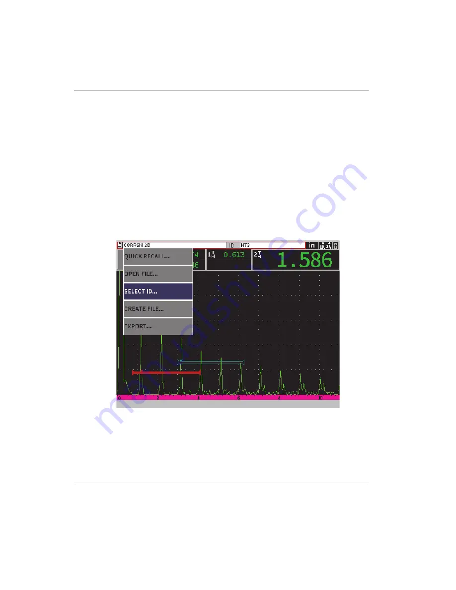
File Identifier Shortcut Menu
The file identifier shortcut menu contains buttons that open data logger setup pages
(see Figure 4-4 on page 28).
Figure 4-4 File identifier shortcut menu
Содержание EPOCH 6LT
Страница 8: ...DMTA 10084 01EN Rev 2 November 2018 Table of Contents viii...
Страница 10: ...DMTA 10084 01EN Rev 2 November 2018 List of Abbreviations x...
Страница 16: ...DMTA 10084 01EN Rev 2 November 2018 Introduction 6...
Страница 20: ...DMTA 10084 01EN Rev 2 November 2018 Chapter 1 10...
Страница 26: ...DMTA 10084 01EN Rev 2 November 2018 Chapter 2 16...
Страница 32: ...DMTA 10084 01EN Rev 2 November 2018 Chapter 3 22...
Страница 68: ...DMTA 10084 01EN Rev 2 November 2018 Chapter 5 58 Figure 5 15 Diagnostic Test setup page...
Страница 109: ...DMTA 10084 01EN Rev 2 November 2018 Calibration 99 Figure 8 7 Calibration Successfully completed...
Страница 110: ...DMTA 10084 01EN Rev 2 November 2018 Chapter 8 100...
Страница 154: ...DMTA 10084 01EN Rev 2 November 2018 Chapter 9 144...
Страница 216: ...DMTA 10084 01EN Rev 2 November 2018 Chapter 11 206 Figure 11 45 Corrosion sidebar menu G2Start...
Страница 220: ...DMTA 10084 01EN Rev 2 November 2018 Appendix 210...
Страница 226: ...DMTA 10084 01EN Rev 2 November 2018 List of Tables 216...
Страница 232: ...DMTA 10084 01EN Rev 2 November 2018 Index 222...


