background image

56

DP21-SAL

The MENU display has the functions for use in various settings. To execute a setting function, place the cursor on the
applicable item and press the SET/OK button. If you are using the mouse, click it on the applicable item.

1

Media Setup

All of the files in the current save folder can be erased with this function.
It is also capable of formatting a connected medium.

 1-1 Erasing files in the specified folder

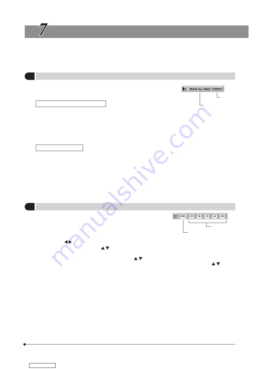
1. Select [ERASE ALL FILES] @ and press the SET/OK button.
2. When the confirmation message is displayed, press the SET/OK button to erase the files. To cancel the operation, press

the MENU button.

}Once [YES] is selected, the all-file erasure operation can no longer be canceled. Confirm well before executing the all-file

erasure.

}The protected images (see p. 55) are not erased.

 1-2 Formatting a medium

1. Select [FORMAT] ² and press the SET/OK button.
2. When the confirmation message is displayed, press the SET/OK button to format the medium. To cancel the operation,

press the MENU button.

}Target of formatting

When multiple USB memories are connected, this operation formats only the first connected one. If a single USB memory
is divided into multiple partitions, it formats only the first drive.

}Once [YES] is selected, the formatting operation can no longer be canceled. Confirm well before executing formatting.
}Formatting erases all of the files in the USB file including the protected images as well as document files.

2

Date/Time Setting

This function sets the date and time of the camera.
The date and time of recording are recorded in the recorded
images.

1. Select the date display format using the cursor buttons.
2. After the above, move the cursor to the date field using the

cursor buttons    .

3. Set the date using the cursor buttons     and press the SET/OK button. The year, month and date should be arranged

in the format selected in step 1.

4. Similarly, set the time of the day using the cursor buttons    .
}The date and time are applied to the system at the moment they are changed using the cursor buttons    , but their

figures on the MENU display are not updated automatically. To check the latest date and time, hide the MENU display
once and display it again.

@

2

Date format setting

Date/Time

ERASE ALL FILES

FORMAT

MENU DISPLAY FUNCTIONS

Downloaded from 

ManualsNet.com

 search engine

Содержание DP21-SAL

Страница 1: ...imum performance and familiarize yourself fully with the use of this device we recommend that you study this manual thoroughly before operating the camera Retain this instruction manual in an easily a...

Страница 2: ...nsible for compliance could void the user s authority to operate the equipment In accordance with European Directive 2002 96 EC on Waste Electrical and Electronic Equipment this symbol indicates that...

Страница 3: ...SETTING OPERATION PLAY 52 55 7 MENU DISPLAY FUNCTIONS 56 62 8 FUNCTIONS INTERLOCKED WITH MICROSCOPE OPERATIONS 8 1 System chart 63 8 2 Connection 64 66 8 3 Operation 67 69 63 69 9 WARNING MESSAGES 70...

Страница 4: ...equipment or other property It may also be used to alert against unsafe practices Indicates commentary for ease of operation and maintenance CAUTION Descriptions in Instruction Manual This Instruction...

Страница 5: ...e power cord and cables could melt and cause electric shock 7 After operation or in case of abnormality be sure to disconnect the power cord from the connector on the AC adapter or from the outlet 8 D...

Страница 6: ...that every unit is connected correctly before operating the product 3 Maintenance and Storage 1 Do not use organic solvents which cause painted and plastic parts to deteriorate Do not use organic sol...

Страница 7: ...disappear be destroyed unexpectedly Be sure to backup the data on regular base Make sure that there is no problem when recording the subjects before acquisition Please note that even though the probl...

Страница 8: ...lithium ion coin battery CR2032 for backing up the calendar function The service life of the battery is 1 to 6 years it is widely variable because the battery power consumption is reduced during oper...

Страница 9: ...es when the specimen contains little white area 7 The measurement results are simply superimposed on the image and no text file or like is created 8 The DP21 SAL can handle files of the FAT and FAT32...

Страница 10: ...ympus for the microscope and camera adapter to be used together DP26 CU Camera cable Control box D21 CB AC adapter Power cord Control box U CBS U CBM BX3 CBH Display cable Monitor display To network L...

Страница 11: ...utton ERASE button MODE button MENU button SET OK button Hand Switch D21 HS MODULE NOMENCLATURE USB ports Control Box D21 CB Front view Pilot LED Rear view Main switch USB ports DC IN connector Displa...

Страница 12: ...r for Vertical Installation Camera head Control box D21 CB 1394b connector 9 pin Stabilizer With 2 clamp screws DVI Protection Adapter AC adapter Input connector Power output plug Downloaded from Manu...

Страница 13: ...emaining image p 24 Exposure time White balance p 35 Exposure adjustment p 27 Scale setting p 38 Scale display area p 40 Zoom p 28 File name p 36 AE lock p 28 Image quality p 31 ISO speed p 32 Meterin...

Страница 14: ...31 Zoom p 28 Protect p 55 Exposure adjustment p 27 Metering area p 27 Exposure time p 37 Date Time p 56 File name p 36 Image No If the save destination is set to a network location the INFO display m...

Страница 15: ...control box D21 CB before proceeding to the connection NOTE When connecting the cable insert the connector plug in the proper direction Example Camera cable Cable side Connector side Fig 2 1 Insert t...

Страница 16: ...ds and cables are vulnerable to bend or twist Do not apply excessive force to them 1 Pass the cable of the AC adapter through the holder on the control box D21 CB and close the holder securely This me...

Страница 17: ...using the sys tem Also contact Olympus immediately Never use an AC adapter other than the designated AC adapter Otherwise a failure of the control box D21 CB camera head or power supply or an incident...

Страница 18: ...d switch D21 HS Otherwise malfunction may result If you use a commercially available USB memory connect it to a USB port of the control box D21 CB The USB memory provided with the DP21 SAL can also be...

Страница 19: ...equires a special driver only the standard functions of the device are available with the DP21 SAL When using a USB keyboard or mouse connect it to a USB port of the control box D21 CB Fig 8 Connectio...

Страница 20: ...e s control to the marking or the voltage specified for photographing Select the recording camera light path on the microscope p 15 p 18 p 19 p 20 p 22 p 23 p 24 Tip Focusing method The live image mag...

Страница 21: ...eft ON Usually this switch does not need to be set to OFF The pilot LED on the camera head lights when it is ON With the standalone system turning the control box D21 CB or hand switch D21 HS OFF auto...

Страница 22: ...and objective in use in the same way The control box D21 CB restarts after completion of the setting See page 57 for the language setting and page 38 for the scale magni fication setting The clock set...

Страница 23: ...Fig 13 2 4 Viewing Hiding the INFO Display When the live image is displayed the INFO display is displayed on the upper right of the screen as shown in the following example which shows the display in...

Страница 24: ...ecting a setting content Press the cursor buttons to place the cursor on the desired setting content When setting a pull down item resolution etc press the cursor buttons after placing the cursor and...

Страница 25: ...monitor screen Low resolution Image observation at a high frame rate displays smooth live images even when the target moves during examina tion etc Binning Sensitivity is higher than other modes Obse...

Страница 26: ...sage can also be switched off by pressing any button other than the main switch If the adjustment fails message white balance setting failed is displayed As this message does not disappear automatical...

Страница 27: ...ining image reaches 0 warning message MEMORY FULL is displayed on the monitor screen Tip The image save destination can be changed p 33 The image can also be saved in the networked PC by advance setti...

Страница 28: ...g A movie can be recorded for up to 5 minutes this period is variable depending on the frame rate and storage medium capacity Movie re cording may stop anytime automatically when the maximum file size...

Страница 29: ...osure time set by AE Auto Exposure Exposure time setting MANUAL mode Sets the exposure time by direct entry of the figure To enter the exposure time directly press the MODE button to select the REC MA...

Страница 30: ...Example 4 3EV 2EV 0 2EV Fig 20 1 3 SPOT Metering Setting REC AUTO mode When the observation target is dispersed in the image the image may become too bright or too dark due to the effect of the backg...

Страница 31: ...ooming Scrolling 1 Press the MENU button to hide the MENU display 2 Press the cursor button or to change the electronic zoom ratio of the live image switches it to 1x 1 1 equal size 2x 4x and switches...

Страница 32: ...an also be used in left right scrolling in the save destination window SET OK MENU or MODE Scale data setting change Shift MENU INFO display view hide switching Shift Cursor button Available only when...

Страница 33: ...rsor on the desired item 3 Press the SET OK button to enter the selection For applied functions and settings see Applied operations p 37 Page select tabs Tab Content Page for the camera s basic functi...

Страница 34: ...save format of the recorded image If the live image resolution is set by Binning 1224 x 960 Binning or 612 x 480 Binning the same number of pixels are set to Size automatically For the live image res...

Страница 35: ...to situations 4 Sharpness Setting Default NORMAL Select the image sharpness The sharpness refers to the degree of contour enhancement of image Three options of NORMAL SOFT and OFF are available The co...

Страница 36: ...n the folder that is created automatically in the medium The folder names as well as the file names of the recorded images are created automatically For details on the folder and file names see Folder...

Страница 37: ...rsor buttons of the hand switch D21 HS and left right scrolling is possible using the Shift left right buttons 1 Place the cursor on and press the cursor button 2 Select the save destination from the...

Страница 38: ...me Color Temperature Specifying the arbitrary color temperature allows you to obtain the color suitable for each color temperature When using DP26 The white balance can be selected from OTWB or Gain U...

Страница 39: ...he file name is used for notation of the year The digits 0 to 9 stand for the year 2000 to 2009 The alphabets A B C stand for the years after 2010 The month in the folder name is expressed with 1 to 9...

Страница 40: ...ay when the recording operation has com pleted The recorded image is displayed after the EXPOSE button is pressed In 5 seconds later it is switched automatically to the live image The REC VIEW functio...

Страница 41: ...No 4 2 Setting a scale 1 Select setting The Scale Setting window shown below appears 2 Change the settings in the Scale Setting window Press the SET OK button to apply the settings and close the Scale...

Страница 42: ...pe Setting Wizard will start 2 Enter the camera adapter magnification objective power etc following the Microscope Setting Wizard Operation using the hand switch D21 HS Adjust the value with the curso...

Страница 43: ...ing is also applied to the measurement related display 6 Image Orientation Setting Default Erect The image can be displayed in one of the four orientations This opera tion is not available in the midd...

Страница 44: ...tatus display The current level is indicated by the blue bar and the maximum level by the red bar Current level Peak level Adjust the focus precisely so that the current level approaches the maximum l...

Страница 45: ...igures with the area The unit used in the measurement result display cannot be changed The display result is displayed near the drawn line or circle It is not possible to change the display position t...

Страница 46: ...f its sides Up to 100 corners can be speci fied per polygon Up to 100 corners can be speci fied per polygon Up to 10 perpendicular lines can be drawn from the reference line Distance of Parallel Lines...

Страница 47: ...of the points you want to specify or left click the mouse if this is in use To measure another circle press the SHIFT button at each of the points to be specified newly 3 To end measurement press the...

Страница 48: ...left click it on END MENU at the top right of the screen 3 Points Angle This function draws two lines based on the three points specified by the user and measures the angle formed by them Measurement...

Страница 49: ...Perpendiculars Measurement target The line passing and 2 reference line is drawn The line orthogonal to the reference line is drawn from 3 and its length is displayed This function draws a line based...

Страница 50: ...t or left click it on END MENU at the top right of the screen Boundary Length Measurement target The point is drawn on the specified position When the SET OK button is pressed or the mouse is right cl...

Страница 51: ...or MENU button if you are using the mouse right click it or left click it on END MENU at the top right of the screen XY Distance Measurement target The line connecting and 2 is drawn and the X distanc...

Страница 52: ...ou are using the mouse right click it or left click it on END MENU at the top right of the screen Cross Line Measurement target The line connecting the specified point and origin point and the cross l...

Страница 53: ...s is in use 3 Select to erase the specified measurement result This function cannot erase more than one measurement result at a time Text Measurement target Press the SET OK button or left click the m...

Страница 54: ...surements results displayed on the screen simultaneously Select to erase all of the measurement results Line text color setup This function displays the measurement lines and texts measured val ues in...

Страница 55: ...play alternately 1 Fig 25 2 1 3 Selecting the Played Image The image to be played can be selected as described below 1 When the PLAY mode is selected the last recorded image in the folder currently se...

Страница 56: ...U button to hide the MENU display 2 Press the cursor button or to change the electronic zoom ratio of the image switches it to 1x 1 1 equal size 2x 4x and switches it to 4x 2x 1 1 equal size 1x Index...

Страница 57: ...the cursor but tons 3 The image in the current cursor position is displayed on the center of the screen 4 While holding the SHIFT button press or to update the thumbnail display page 5 Press the SET...

Страница 58: ...t symbol To unprotect an image select a protected image and press the PRO TECT button again 9 Measurement of played image Measurement is also possible with played images The operating pro cedures are...

Страница 59: ...are connected this operation formats only the first connected one If a single USB memory is divided into multiple partitions it formats only the first drive Once YES is selected the formatting operat...

Страница 60: ...he language used in the operation can be selected from English and Japanese When the button is selected the Language Setting Wizard shown below appears Select the desired language by following this wi...

Страница 61: ...minutes and 10 minutes The sleep mode is canceled when the hand switch D21 HS mouse or keyboard is controlled A certain time may be required before the setting change is applied 6 Maintenance Setting...

Страница 62: ...A If nothing is displayed due to inappropriate resolution set the main switch to OFF then ON again In about 30 seconds after the instrument is started up the AE Lock LED lights up for about 1 second P...

Страница 63: ...ter the setting items Member IP address DNS server name by following the instructions in the Network Connection Setting window Enter the setting items according to the connection environment being use...

Страница 64: ...rmation please visit the following website For Life Science http microscope olympus global com en ga support software For Industrial Solutions http www olympus ims com en service and support downloads...

Страница 65: ...pop up menus can be used to control the following functions MODE switching MENU INFO display hiding Zoom setting Index 1x 1 1 equal size 2x 4x Settings of MENU display items Move the cursor with the...

Страница 66: ...croscope Control box U CBS U CBM BX3 CBH Hand switch for exposure U HSEXP Guidance The guidance on the operating procedures of the microscope and cam era can be displayed Control box U CBS U CBM BX3 C...

Страница 67: ...nated module is used Be sure to set the POWER switch of the control box for coded units U CBS to OFF in the high position before connecting cables When connecting each connector align the orientation...

Страница 68: ...apter for U CBM RS232C cable D21 CB RS232C connector The OUT 1 to 4 connectors are universal type connectors The U D7REA can be connected to any of them Connection of BX3 CBH BX3 CBH RS232C connector...

Страница 69: ...adjustment knob on the left or right Please note that if the attaching position of U HSEXP is too close to the coarse adjustment knob it may touch the pre focusing lever 3 Clean the final fixing posi...

Страница 70: ...ched ON If you have already started up the DP21 SAL the objective magnifications can be input with the following procedure Displaying the scale Set ON OFF in the Menu window to ON to display the scale...

Страница 71: ...epiece and input the magnifications and memory numbers of the objectives that are present 5When the information of all of the revolving nosepiece positions has been input press the SET OK button of th...

Страница 72: ...hod of connection to the U CBS See page 66 for the method of installation on the microscope It cannot be recorded by the shutter switch Use the hand switch D21 HS to start finish recording Guidance fu...

Страница 73: ...ed in case of an error with low severity when the operation can be continued by redoing etc The message is kept displayed until OK ANY KEY is clicked Confirm Confirmation of an operation such as image...

Страница 74: ...ay area 1280 x 960 1280 x 960 1024 x 768 800 x 600 Image display speed Frame rate DP21 Live image 15 fps Displayed pixels 1600 x 1200 27 fps Displayed pixels 800 x 600 DP26 Live image 7 fps Displayed...

Страница 75: ...0 V 50 60 Hz 2 A Power consumption Control Box D21 CB Max consumption 24 2 W During shutdown 0 W Apparent power Approx 2 0 VA Standby mode 1 4 W or less Operating environment Indoor use Altitude Max 2...

Страница 76: ...Insert all the way into the connector The LAN cable is connected improp erly applicable only when the save destination is a networked PC Connect the LAN cable correctly The save destination PC cannot...

Страница 77: ...t the brightness again A fluorescent lamp is used Use a light source other than a fluo rescent light The colors in the image are strange The white balance is erroneous be cause of a wrong color temper...

Страница 78: ...The control box is not recognized Set the main switches of the control box BX3 CBH etc and the control box D21 CB and set the switches to ON in the order of 1 control box BX3 CBH etc 2 control box D2...

Страница 79: ...rtified Cord A power supply cord should be certified by one of the agencies listed in Table 1 or comprised of cordage marked with an agency marking per Table 1 or marked per Table 2 The fittings are t...

Страница 80: ...band f r Elektrotechnik VE Danmarks Elektriske Materialkontroll DEMKO National Standards Authority of Ireland NSAI Norges Elektriske Materiellkontroll NEMKO Asociacion Electrotecnica Y Electronica Esp...

Страница 81: ...MEMO Downloaded from ManualsNet com search engine...

Страница 82: ...MEMO Downloaded from ManualsNet com search engine...

Страница 83: ...Downloaded from ManualsNet com search engine...

Страница 84: ...AX8233 02 Manufactured by Distributed by Downloaded from ManualsNet com search engine...

Отзывы: