


2KL/2KK
1-3-35
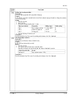
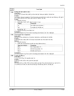
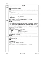
U101
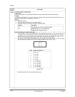
Setting the other high voltages
Description
Changes the developing bias clock, the transfer and separation charging output timing.
Purpose
To check the developing bias clock, the transfer and separation charging output timing. Do not change the
preset value.
Method
Press the start key.
Setting
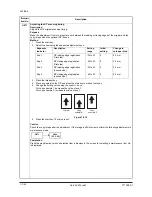
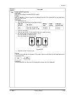
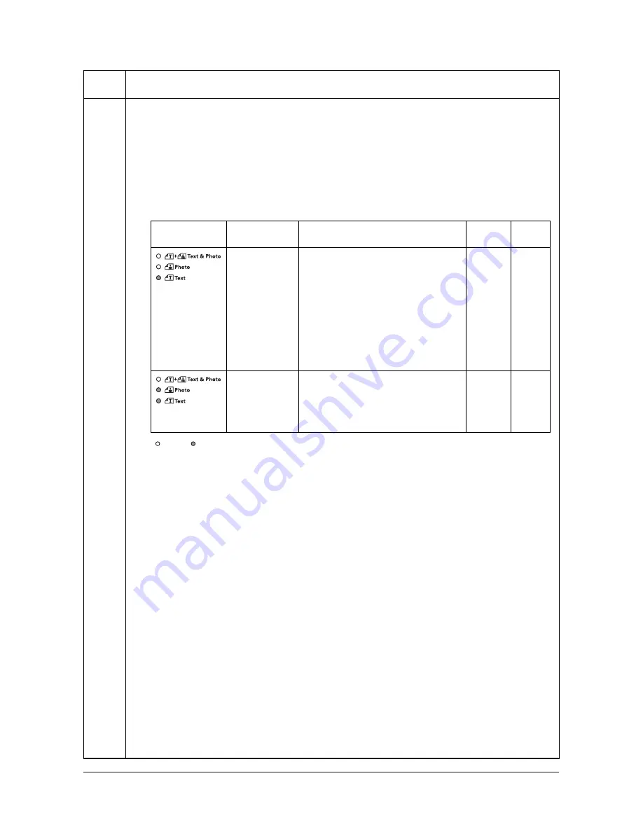
1. Select the group to be set or checked using the image mode selection key.
2. Select the item to be set using the exposure adjustment keys.
: Off,
: On
3. Change the setting using the zoom +/- keys.
4. Press the start key. The value is set.
Supplement
While this maintenance item is being executed, copying from an original is available in interrupt copying mode
(which is activated by pressing the interrupt key).
Completion
Press the stop/clear key. The screen for selecting a maintenance item No. is displayed.
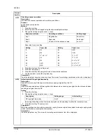
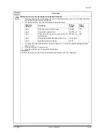
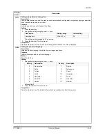
Maintenance
item No.
Description
Image mode
LEDs
Exposure
indicator
Description
Setting
range
Initial
setting
Exp. 1 (lit)
Developing bias clock frequency (copier) 2 to 255
27
Exp. 2 (lit)
Developing bias clock duty (copier)
1 to 99
45
Exp. 3 (lit)
Developing bias clock frequency (printer) 2 to 255
22
Exp. 4 (lit)
Developing bias clock duty (printer)
1 to 99
45
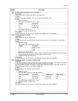
Exp. 5 (lit)
Transfer control voltage (large size)
0 to 255
123
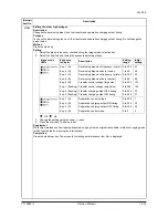
Exp. 1 (flashing) Transfer control voltage (small size)
0 to 255
126
Exp. 2 (flashing) Transfer charging output OFF timing
0 to 255
33
Exp. 3 (flashing) Transfer charging output ON timing
0 to 255
31
Exp. 1 (lit)
Separation control voltage
0 to 255
1
Exp. 2 (lit)
Separation charging output ON timing
0 to 255
20
Exp. 3 (lit)
Separation charging output OFF timing
0 to 255
42
Exp. 4 (lit)
Separation control mode
0 to 3
2
Y110980-1 Service Manual
Содержание d-Copia 1800
Страница 1: ...d Copia 1800 d Copia 2200 Digital Copier SERVICE MANUAL Code Y110980 1...
Страница 4: ...This page is intentionally left blank...
Страница 10: ...This page is intentionally left blank...
Страница 14: ...2KL 2KK This page is intentionally left blank...
Страница 20: ...2KL 2KK 1 1 6 This page is intentionally left blank Service Manual Y110980 1...
Страница 38: ...2KL 2KK 1 2 18 This page is intentionally left blank Service Manual Y110980 1...
Страница 108: ...2KL 2KK 1 3 70 This page is intentionally left blank Service Manual Y110980 1...
Страница 142: ...2KL 2KK 1 4 34 This page is intentionally left blank Service Manual Y110980 1...
Страница 198: ...2KL 2KK 1 5 56 This page is intentionally left blank Service Manual Y110980 1...
Страница 224: ...2KL 2KK 2 2 6 This page is intentionally left blank Service Manual Y110980 1...
Страница 240: ...2KL 2KK 2 3 16 This page is intentionally left blank Service Manual Y110980 1...
Страница 271: ...INSTALLATION GUIDE FOR PAPER FEEDER...
Страница 285: ...INSTALLATION GUIDE FOR DUPLEX UNIT...
Страница 294: ...INSTALLATION GUIDE FOR Printing System Z...
Страница 297: ...UPDATING STATUS DATE UPDATED PAGES PAGES CODE 09 2009 1ST EDITION 297 Y110980 1...