


User Manual LR-16F
OMEN-16F-202012
14
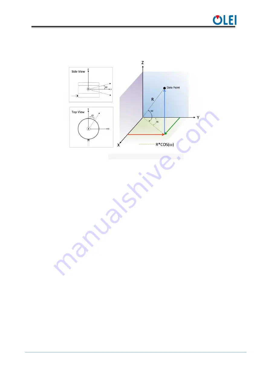
The horizontal offset of each channel of the radar is set as A
The vertical offset of each channel of the radar is set as B
The spatial coordinate system of each channel of the radar is set as X, Y, Z
Figure 11
Coordinate transformation definition
For program analysis, see “Appendix E: 3D Lidar Coordinate Code Analysis” for reference.
8.2.
Azimuth
Each data package records 12 azimuth values, which are located after the 0xFFEE flag
of each data block. The azimuth angles of the last 16 laser beams of each data block are
obtained through interpolation calculation. See the next section for specific methods.
The specific calculation method and steps of the azimuth angle are shown in the
following example:
1) Obtain the azimuth value: 0x21 & 0x63
2) Interchange of high byte and low byte: 0x63 & 0x21
3) Combine into an unsigned hexadecimal number: 0x6321
4) Converted to decimal number: 25377
5) Multiply by the minimum resolution: 0.01°
6) Result: 253.77°
The 0° of the azimuth is coaxial with the base of lidar main body,and in the opposite
direction.
8.3.
Azimuth interpolation
LR-16F can directly obtain the azimuth angle of the first 16-line laser pulse sequence in
each data block through the data package, and then obtain the azimuth angle value of the
second 16-line laser pulse sequence through interpolation calculation.
Assuming that among the 24 laser sequences of 12 data blocks, the adjacent 3 sequence
numbers are N, N+1, and N+2, and the values of N and N+2 are known. The simplest and
most direct method is to calculate the azimuth value of N+1 through N and N+2 interpolation
(By default, the rotation speed is constant during the whole process). For the interpolation
procedure, see “Appendix F: Interpolation Code Analysis” for reference.


