


4742-E P-81
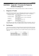
SECTION 3 Appendix 1. Procedure for Replacing External Cooling Fan
SECTION 3 Appendix 1. Procedure for Replacing
External Cooling Fan
Eeospcsa3001
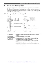
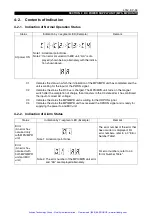
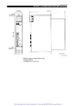
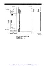
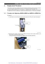
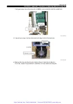
Follow the procedure below to replace the external cooling fan of the MIV unit or MPS unit.
1.
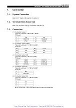
Diagnosis of Trouble
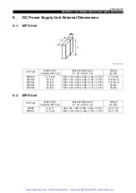
Eeospcsa3002
If the external cooling fan is broken down, the temperature of the heat sink rises abruptly and the fol-
lowing alarms are issued. (See "4. Indication of Operating Status" in Section 1 and Section 2.)
When these alarms occur, check if the external cooling fan rotates in the power-on state. If it is
stopped though the power is turned on, replace the external cooling fan in the following procedure.
2.
Part Number
Eeospcsa3003
The main body of the cooling fan, drip-proof bushing and connector machined in advance are regis-
tered as a set with the following part numbers so that the external cooling fan can be replaced eas-
ily.
The external cooling fan varies according to the unit; prepare the external cooling fan matching the
broken unit.
With MIV06 or MIV08
: Inverter bridge error
(The 7-segment LED shows "EL" and "13" alternately.)
With MIV15 to MIV45
: Inverter overheat
(The 7-segment LED shows "AL" and "05" alternately.)
With MPS10
: Power element error
(The 7-segment LED shows "09.")
With MPS20 to
MPS60
: Heat sink overheat
(The 7-segment LED shows "13.")
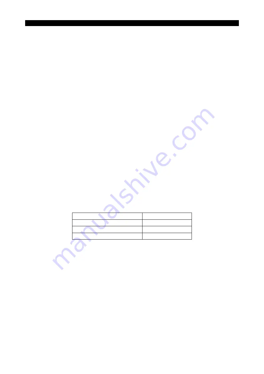
Unit
Part No.
MIV06, MIV08, MPS10
E1310-528-053
MIV15, MIV22, MPS20, MPS30
E1310-528-054
MIV30, MIV45, MPS45, MPS60
E1310-528-055
Artisan Technology Group - Quality Instrumentation ... Guaranteed | (888) 88-SOURCE | www.artisantg.com


