4742-E P-56
SECTION 1 INVERTER UNIT (MIV UNIT)
EIOSPCSA1037R01
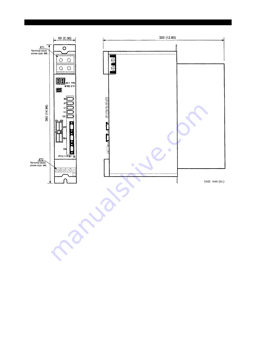
MIV Unit for VAC MotorsUnit Type: MIV04-3Unit Weight: 5.7 kg (12.5 lb)
Artisan Technology Group - Quality Instrumentation ... Guaranteed | (888) 88-SOURCE | www.artisantg.com
Страница 1: ...service in house repair center WE BUY USED EQUIPMENT Sell your excess underutilized and idle used equipment We also offer credit for buy backs and trade ins www artisantg com WeBuyEquipment REMOTE IN...
Страница 2: ...RIVE UNIT MOTIONCONTROLSYSTEM MCS MCSII MAINTENANCE MANUAL 5th Edition Pub No 4742 E R1 SEH4 001 R5 Mar 2003 Artisan Technology Group Quality Instrumentation Guaranteed 888 88 SOURCE www artisantg com...
Страница 3: ...ire may be cause due to short circuit 6 When manufacturing cables used for connecting units make sure that the size of cables matches the carrying current Especially power cables must be manufactured...
Страница 4: ...Axes 35 6 2 MIV Unit for Spindle M tool Spindle Sub Spindle 37 6 3 SWM Monitor Unit 39 7 Connection 44 7 1 System Connection 44 7 2 Terminal Block Screw Size 46 7 3 Connectors 46 8 MIV Unit External D...
Страница 5: ...Size 74 7 3 Connectors 74 8 DC Power Supply Unit External Dimensions 75 8 1 MPS Unit 75 8 2 MPR Unit 75 SECTION 3 Appendix 1 Procedure for Replacing External Cooling Fan 81 1 Diagnosis of Trouble 81 2...
Страница 6: ...eripheral is shown below A DC power supply is connected to MIV unit to supply 300 VDC and 24 VDC control power MIV unit communicates with peripherals through the servo link the encoder link and the co...
Страница 7: ...cating unit capacity inverter control board type motor type and control ROM type as shown below EIOSPCSA1002R01 MIV unit type name is shown at the front of the unit either by seal or printed character...
Страница 8: ...otor capacity 1 8 kW 2 4 hp MIV02 1 PU 1 1006 2212 1 axis control inverter unit Applicable motor capacity 2 8 kW 3 73 hp MIV03 1 PU 1 1006 2213 1 axis control inverter unit Applicable motor capacity 3...
Страница 9: ...W 2 4 hp 2 4 hp MIV0102 1 PU 1 1006 2225 2 axis control inverter unit Applicable motor capacity 1 8 kW 2 8 kW 2 4 hp 3 73 hp MIV0202 1 PU 1 1006 2226 2 axis control inverter unit Applicable motor capa...
Страница 10: ...ntrol board 1 Display card MFP1 CARD 1 1006 2105 Card with status indicator Inverter unit MIV04 3 PU 1 1006 2254 Inverter unit Applicable motor capacity 1 1 kW 1 5 hp MIV06 3 PU 1 1006 2256 Inverter u...
Страница 11: ...its Eeospcsa1007 Construction of MIV unit is shown below 1 Construction of MIV01 to MIV05 and MIV0101 to MIV0404 EIOSPCSA1004R01 2 Construction of MIV06 and MIV08 EIOSPCSA1005R01 Artisan Technology Gr...
Страница 12: ...1 INVERTER UNIT MIV UNIT 3 Construction of MIV15 and MIV22 EIOSPCSA1006R01 4 Construction of MIV30 and MIV45 EIOSPCSA1007R01 Artisan Technology Group Quality Instrumentation Guaranteed 888 88 SOURCE...
Страница 13: ...0 75 1 BL MC50J 20 1 1 33 BL MC100J 12 1 2 1 6 BL MC50J 30 1 5 2 BL MC75J 20 1 5 2 BL MC150J 12 1 8 2 4 BL MC95J 20 2 2 67 MIV02 1 MIV0102 1 M MIV0202 1 L M MIV0203 1 L MIV0204 1 L BL MC100J 20 2 2 67...
Страница 14: ...203 1 L MIV0204 1 L BL MC50J 30 1 5 2 BL MC75J 20 1 5 2 BL MC150J 12 1 8 2 4 MIV03 1 MIV0103 1 M MIV0203 1 M MIV0303 1 L M BL MC95J 20 2 2 67 BL MC100J 20 2 2 67 BL MC75J 30 2 2 2 93 BL MC200J 12 2 4...
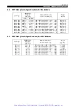
Страница 15: ...Rated Motor Output kW hp MIV Unit VAC 2 2 1 1 2 93 1 46 MIV04 3 VAC 3 7 2 2 4 93 2 93 MIV06 3 VAC 5 5 3 7 7 33 4 93 VAC 7 5 5 5 10 7 33 VAC 11 7 5 14 67 10 MIV08 3 VAC 15 11 20 14 67 MIV15 3 VAC 18 5...
Страница 16: ...of MIV units differs according to the unit capacity the control board and the software ROM When changing a unit make sure to use the unit of the same type EIOSPCSA1008R01 WARNING MIV unit has a large...
Страница 17: ...place the unit according to the following instructions 1 MIV08 1 for the PREX motor does not have DBR8 NOTICE 2 Replacement of MIV14 3 Replace MIV14 3 with the upper grade unit MIV15 3 In this case it...
Страница 18: ...les between DBR8 terminal block and Cables between DBR8 connector DBR and Cables between DBR8 connector DC and After replacement MIV06DB 1 only XT1 U V W U V W AXIS UNIT DC DBR UNIT TYPE DBR8 DCA DCB...
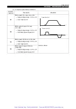
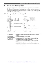
Страница 19: ...wo dis play modes normal operation status display mode and alarm status display mode are provided and at the occurrence of an alarm the 7 segment LED displays an error number so that the cause of the...
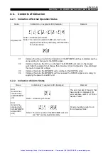
Страница 20: ...on 7 segment LED s light at both L and M side At start up 1 At L side only Indication changes in the following order 3 4 5 6 J C P In the case of 1 axis specification only L side 7 segment LED lights...
Страница 21: ...to the axis control specification initialization phase 3 4 Conversion and check process of the data transmitted in the initialization phase 3 initialization phase 4 5 Synchronous processing with the...
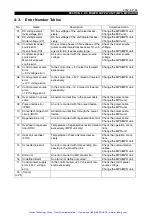
Страница 22: ...ry device Exception error Note 1 Displays EL and 01 alternately L side Exception error No 01 Displays EH and 02 alternately M side Exception error No 02 Alarm Note 2 Displays AL and 13 alternately L s...
Страница 23: ...AAC0 Hex YYYY Absolute value of 12 V power detected voltage Normal range 13 44 V to 11 046 V Allowable data range 8D40 to AA00 Hex For MCS II XXXX Detected voltage of 12 V power Normal range 11 234 t...
Страница 24: ...register 11 Control power supply 5 V error In case of MCS Error status register In case of MCS II XXXX Fixed at FFFF Hex YYYY 5 V detected voltage 5 V 4D80 Hex Normal range 4 63 to 5 44 V Allowable da...
Страница 25: ...5 DMA address error DMAC DTC address error An error occurred with CPU processing XXXXXXXX PC at the occurrence of the error Change the MIV unit 36 Undefined trap instruc tion An error occurred with CP...
Страница 26: ...larm number 4 Not defined If X alarm number 5 Not defined If X alarm number 6 Not defined Check the source voltage Check the operation conditions Check the error No of MPS MPR unit Change the MPS MPR...
Страница 27: ...detection of overload YYYY Cumulative data at the detection of overload Check the operation conditions Reduce the cutting load torque Check the servo data file Change the MIV unit 07 Commercial power...
Страница 28: ...communication with the motor attached encoder bit 11 Undefined bit 10 1 AT mode send loop error bit 9 1 Receive IF section data number over error bit 8 Undefined bit 7 Undefined bit 6 1 Modulation co...
Страница 29: ...tion information 3 Incompatibility of mufti turn detection range 4 Incompatibility of communication protocol version However when the MCS detected abnormal voltage applied to the fuse used in the powe...
Страница 30: ...f gear teeth Check the servo data file Change the mag netic encoder Change the mag netic encoder cable 18 Resolver error The resolver failed to detect the position data XXXXXXXX 1 Disconnection error...
Страница 31: ...YY XXXX Wire breakage position 0000 Hex Immediately upstream the corresponding unit 8000 Hex Upstream the corresponding unit YYYY Servo link error status at the detection of error Change the servo lin...
Страница 32: ...rned ON 0031 Hex Undefined bit data of the servo link B buffer is turned ON 0040 Hex Mode was changed to AT mode although time synchronization instruction has not been received YYYY Error data If XXXX...
Страница 33: ...3 In an axis with a limited stroke its stroke was exceeded Change the MIV unit In the case of BL motor Change the motor attached encoder Change the encoder link cable In the case of VAC motor Change...
Страница 34: ...of torque in 3 2 msec period 2 12 MAXTRQ If Tv 0 4 msec 7FFF Hex corresponds to the maximum momentary torque If Tv 0 8 msec 3FFF Hex corresponds to the maximum momentary torque YYYY Detected accelerat...
Страница 35: ...activated since the motor load exceeded the specified value XXXXYYYY XXXX of the protection curve at the detection of overload YYYY Cumulative data at the detection of overload Check the operation con...
Страница 36: ...ection of error Displayed in hexadecimal 01 Hex 0 volts Displayed in hexadecimal 80 Hex 300 volts Check the source voltage Check the power cable Check the MPS MPR unit 20 Motor overheat There is a pos...
Страница 37: ...MIV units according to the axis names For the setting of a controller ID number a 5 bit switch is provided set the ID number refer ring to the controller ID table 2 axis spec MIV unit for BL motors S...
Страница 38: ...axis LYA RCA Loader Y axis or loader R side Y axis Robot RCA axis 13 ON ON ON 13th NC controlled axis LZA Loader Z axis or loader R side Z axis 14 ON ON ON 14th NC controlled axis LXB Loader L side X...
Страница 39: ...ave axis of the synchronized 3rd axis 15 ON ON ON ON 1st PLC controlled axis MA Magazine A rotation axis 16 ON 2nd PLC controlled axis MB Magazine B rotation axis multi magazine spec 17 ON ON 3rd PLC...
Страница 40: ...e monitor terminal The MIV unit equipped with ICB F or ICB H allows observation of the waveform of the servo at the monitor terminal of the SWM monitor unit if an SWM monitor unit is connected 6 1 MIV...
Страница 41: ...n 1 V M2 Motor output torque of 2nd axis M side Output voltage range 3 V to 3 V Unit Motor peak torque at 3 V M3 Motor speed of 1st axis L side Output voltage range 3 V to 3 V Unit 1562 min 1 V Same a...
Страница 42: ...ER UNIT MIV UNIT 6 2 MIV Unit for Spindle M tool Spindle Sub Spindle 6 2 1 Arrangement of Monitor Terminals Eeospcsa1022 EIOSPCSA1025R01 Artisan Technology Group Quality Instrumentation Guaranteed 888...
Страница 43: ...4T Value T differs according to speed M1 Motor speed Output voltage range 3 V to 3 V Unit 1562 min 1 V M2 Motor output torque Output voltage range 3 V to 3 V Unit Motor peak torque at 3 V R1 Resolver...
Страница 44: ...n to the connector with which the SWM unit is connected refer to the fig ure below 1 SWM unit connection drawing for MIV 1 EIOSPCSA1043R01 2 SWM unit connection drawing for MIV 3 EIOSPCSA1042R01 UNIT...
Страница 45: ...put voltage range 3 V to 3 V Unit 1562 min 1 V M2 Motor output torque of 1st axis on L side Output voltage range 3 V to 3 V Unit Motor peak torque at 3 V M3 Motor speed of 2nd axis on M side Output vo...
Страница 46: ...ht 2 6 to 4 6 V 3 3 V when gap is normally adjusted B B phase signal of magnetic encoder Vpp in the figure on the right 2 6 to 4 6 V 3 3 V when gap is normally adjusted Z Z phase signal of magnetic en...
Страница 47: ...rque of 1st axis on L side Output voltage range 3 V to 3 V Unit Motor peak torque at 3 V M3 Motor speed of 2nd axis on M side Output voltage range 3 V to 3 V Unit 1562 min 1 V Same as above M4 Motor o...
Страница 48: ...3 V when gap is normally adjusted The signal oscillates around 2 5 V line B B phase signal of magnetic encoder Vpp in the figure on the right 2 6 to 4 6 V 3 3 V when gap is normally adjusted Z Z phase...
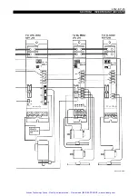
Страница 49: ...ction Eeospcsa1024 This section shows the connection diagram of MCS and the connector pin layout of MIV unit 7 1 System Connection Eeospcsa1025 EIOSPCSA1029R01 Artisan Technology Group Quality Instrum...
Страница 50: ...4742 E P 45 SECTION 1 INVERTER UNIT MIV UNIT EIOSPCSA1030R01 Artisan Technology Group Quality Instrumentation Guaranteed 888 88 SOURCE www artisantg com...
Страница 51: ...C2 Type manufacturer 53460 0611 Molex Pin layout 4 Connector name 232 Type manufacturer 53460 0611 Molex Pin layout 5 Connector name E1M Type manufacturer 53460 0611 Molex Pin layout 1 N C 2 N C 3 SL...
Страница 52: ...r 1 178137 2 AMP Pin layout Note 1 Not necessary for 1 axis spec MIV unit 11 Connector name EPG Type manufacturer D02 M15SAG 13L9 JAE Pin layout 1 12 V 2 SG 3 ELD S 4 ELD N S 5 N C 6 N C 1 N C 2 N C T...
Страница 53: ...14 Connector name AC Type manufacturer 1 179276 2 AMP Pin layout 1 R1 6 R2 11 FG1 2 S1 7 S3 12 FG3 3 S2 8 S4 13 FG4 4 N C 9 N C 14 N C 5 OL 10 OL COM 15 FG2 1 RLMSCHG 6 N C 11 RLMSCOM 2 RHMSCHG 7 N C...
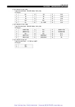
Страница 54: ...V22 1 1 8 2 4 2 8 3 7 3 0 4 4 0 5 3 4 8 6 4 6 0 8 7 5 10 15 0 20 22 0 30 380 60 325 14 96 2 36 12 79 380 60 325 14 96 2 36 12 79 380 60 325 14 96 2 36 12 79 380 60 325 14 96 2 36 12 79 380 60 325 14 9...
Страница 55: ...4 96 2 36 12 79 380 60 325 14 96 2 36 12 79 380 60 325 14 96 2 36 12 79 380 100 325 14 96 3 94 12 79 380 100 325 14 96 3 94 12 79 380 100 325 14 96 3 94 12 79 6 3 13 9 6 3 13 9 6 3 13 9 6 3 13 9 6 3 1...
Страница 56: ...RTER UNIT MIV UNIT EIOSPCSA1032R01 MIV Unit 1 axis Specification for BL Motors Unit Type MIV01 1 to MIV05 1 Unit Weight 5 7 kg 12 5 lb Artisan Technology Group Quality Instrumentation Guaranteed 888 8...
Страница 57: ...ER UNIT MIV UNIT EIOSPCSA1033R01 MIV Unit 1 axis Specification for BL Motors Unit Type MIV06DB 1 to MIV08DB 1 Unit Weight 7 5 kg 16 5 lb Artisan Technology Group Quality Instrumentation Guaranteed 888...
Страница 58: ...TER UNIT MIV UNIT EIOSPCSA1034R01 MIV Unit 1 axis Specification for BL Motors Unit Type MIV15 1 to MIV22 1 Unit Weight 11 2 kg 24 6 lb Artisan Technology Group Quality Instrumentation Guaranteed 888 8...
Страница 59: ...ER UNIT MIV UNIT EIOSPCSA1035R01 MIV Unit 2 axis Specification for BL Motors Unit Type MIV0101 1 to MIV0303 1 Unit Weight 6 3 kg 13 9 lb Artisan Technology Group Quality Instrumentation Guaranteed 888...
Страница 60: ...ER UNIT MIV UNIT EIOSPCSA1036R01 MIV Unit 2 axis Specification for BL Motors Unit Type MIV0104 1 to MIV0404 1 Unit Weight 7 8 kg 17 2 lb Artisan Technology Group Quality Instrumentation Guaranteed 888...
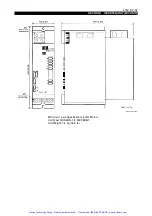
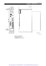
Страница 61: ...SECTION 1 INVERTER UNIT MIV UNIT EIOSPCSA1037R01 MIV Unit for VAC Motors Unit Type MIV04 3 Unit Weight 5 7 kg 12 5 lb Artisan Technology Group Quality Instrumentation Guaranteed 888 88 SOURCE www art...
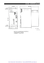
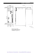
Страница 62: ...ION 1 INVERTER UNIT MIV UNIT EIOSPCSA1038R01 MIV Unit for VAC Motors Unit Type MIV06 3 to MIV08 3 Unit Weight 7 3 kg 16 1 lb Artisan Technology Group Quality Instrumentation Guaranteed 888 88 SOURCE w...
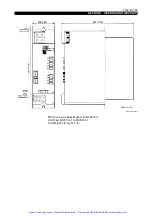
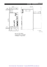
Страница 63: ...ON 1 INVERTER UNIT MIV UNIT EIOSPCSA1039R01 MIV Unit for VAC Motors Unit Type MIV14 3 to MIV22 3 Unit Weight 11 2 kg 24 6 lb Artisan Technology Group Quality Instrumentation Guaranteed 888 88 SOURCE w...
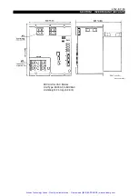
Страница 64: ...ON 1 INVERTER UNIT MIV UNIT EIOSPCSA1040R01 MIV Unit for VAC Motors Unit Type MIV30 3 to MIV45 3 Unit Weight 24 0 kg 52 8 lb Artisan Technology Group Quality Instrumentation Guaranteed 888 88 SOURCE w...
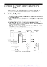
Страница 65: ...ected to MIV unit to supply 300 VDC and 24 VDC control power A DC power supply unit executes communications with MIV unit through the converter link There are two types of DC power supply unit accordi...
Страница 66: ...er supply unit names consist of codes indicating regeneration method and unit capacity EIOSPCSA2002R01 DC power supply unit type name is shown at the front of the unit either by seal or printed charac...
Страница 67: ...ion type unit MPS10 PU 1 1006 2200 DC power supply unit Continuous power supply capacity 11 kW 15 hp MPS20 PU 1 1006 2201 DC power supply unit Continuous power supply capacity 20 kW 27 hp MPS30 PU 1 1...
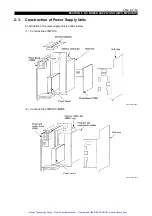
Страница 68: ...tion of Power Supply Units Eeospcsa2007 Construction of a power supply unit is shown below 1 Construction of MPS10 EIOSPCSA2004R01 2 Construction of MPR10 MPR5 EIOSPCSA2005R01 Artisan Technology Group...
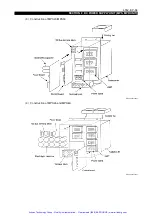
Страница 69: ...DC POWER SUPPLY UNIT MPS MPR UNIT 3 Construction of MPS20 MPS30 EIOSPCSA2006R01 4 Construction of MPS45 and MPS60 EIOSPCSA2007R01 Artisan Technology Group Quality Instrumentation Guaranteed 888 88 SOU...
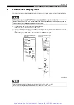
Страница 70: ...method and unit capac ity When changing a unit make sure to use the unit of the same type EIOSPCSA2008R01 WARNING A DC power supply unit MPS MPR has a large capacitance capacitor in the unit When cha...
Страница 71: ...upper terminal block After pushing in the lock lightly tilt the cover 10 deg to the front and the cover can be taken out upward Plastic cover at the lower terminal block After pushing in the lock lig...
Страница 72: ...EIOSPCSA2009R01 7 segment LED Indicates the operation status or an error number at the occurrence of an error DC bus charged status indication lamp Indicates that the DC bus is being charged 24 V powe...
Страница 73: ...completion of charge then transfers to the C3 state after it has confirmed the input of correct AC voltage C3 Indicates the status the MPS MPR unit is waiting for the ORPON signal C4 Indicates the st...
Страница 74: ...ge the MPS MPR unit 08 Over current in power cable Abnormal current flow in the power cable Check the power cable Change the MPS unit 09 Power device error IPMF An error occurred with the power device...
Страница 75: ...occurred with CPU processing Change the MPS unit 42 Undefined interruption An error occurred with CPU processing Change the MPS unit 43 DMAC interruption An error occurred with CPU processing Change t...
Страница 76: ...t is not necessary to set a controller ID number With MPS unit however set the 5 bit controller ID switch to all OFF since the switch is used as the mode selection switch changing to the adjustment mo...
Страница 77: ...unit has the monitor terminals to allow observation of waveform of power source voltage and current by connecting an oscilloscope to these terminals 6 1 Arrangement of Monitor Terminals Eeospcsa2016...
Страница 78: ...o 3 V outputs an internal signal Ets Esr Power source voltage Output voltage range 2 5 V to 2 5 V Unit V multiplication factor 1 151 Vpp 3 8 V for 200 V power source T 16 7 msec for 60 Hz power source...
Страница 79: ...e manufacturer 1 178137 2 AMP Pin layout 3 Connector name OPR Type manufacturer 178303 2 AMP Pin layout 4 Connector name MC Type manufacturer 1 179276 2 AMP Pin layout 5 Connector name ACA Type manufa...
Страница 80: ...3 20 27 30 40 45 60 60 80 380 100 325 14 96 3 94 12 79 380 150 325 14 96 5 91 12 79 380 150 325 14 96 5 91 12 79 380 300 325 14 96 11 8 12 79 380 300 325 14 96 11 8 12 79 7 7 16 9 11 8 26 0 11 8 26 0...
Страница 81: ...2 DC POWER SUPPLY UNIT MPS MPR UNIT EIOSPCSA2019R01 MPS Unit Power Regeneration Type Unit Type MPS10 Unit Weight 7 7 kg 16 94 lb Artisan Technology Group Quality Instrumentation Guaranteed 888 88 SOUR...
Страница 82: ...POWER SUPPLY UNIT MPS MPR UNIT EIOSPCSA2020R01 MPR Unit Resistor Regeneration Type Unit Type MPS20 to 30 Unit Weight 11 8 kg 26 0 lb Artisan Technology Group Quality Instrumentation Guaranteed 888 88...
Страница 83: ...C POWER SUPPLY UNIT MPS MPR UNIT EIOSPCSA2021R01 MPR Unit Resistor Regeneration Type Unit Type MPS45 to 60 Unit Weight 25 kg 55 lb Artisan Technology Group Quality Instrumentation Guaranteed 888 88 SO...
Страница 84: ...DC POWER SUPPLY UNIT MPS MPR UNIT EIOSPCSA2022R01 MPR Unit Resistor Regeneration Type Unit Type MPR5 Unit Weight 5 4 kg 11 9 lb Artisan Technology Group Quality Instrumentation Guaranteed 888 88 SOUR...
Страница 85: ...DC POWER SUPPLY UNIT MPS MPR UNIT EIOSPCSA2023R01 MPR Unit Resistor Regeneration Type Unit Type MPR10 Unit Weight 8 0 kg 17 6 lb Artisan Technology Group Quality Instrumentation Guaranteed 888 88 SOU...
Страница 86: ...g procedure 2 Part Number Eeospcsa3003 The main body of the cooling fan drip proof bushing and connector machined in advance are regis tered as a set with the following part numbers so that the extern...
Страница 87: ...n unit from the control box and replace the external cooling fan in the following procedure 3 1 Procedure for Replacing MIV06 to MIV22 and MPS10 to MPS30 Fan Eeospcsa3005 Procedure 1 Loosen the two sc...
Страница 88: ...30 EIOSPCSA3003R01 3 Loosen four screws to remove the external cooling fan from the heat sink EIOSPCSA3004R01 4 Remove the drip proof bushing and remove the set of external cooling fan From now revers...
Страница 89: ...DC bus terminal block cover and front panel EIOSPCSA3005R01 2 Loosen five screws to remove the DC bus board Two of the five screws have different length be careful during assembly of new fan EIOSPCSA...
Страница 90: ...a3007 The drip proof bushing of MIV06 MIV08 or MPS10 used for the machine delivered before June 1999 is fixed with silicone rubber for the enhancement of water tightness of the motor cable port of the...
Страница 91: ...me DRIVE UNIT MOTION CONTROL SYSTEM MCS MCSII MAINTENANCE MANUAL Manual No SEH4 001 R Edition Date Revision 01 Apr 01 First 05 Mar 03 5th Artisan Technology Group Quality Instrumentation Guaranteed 88...
Страница 92: ...service in house repair center WE BUY USED EQUIPMENT Sell your excess underutilized and idle used equipment We also offer credit for buy backs and trade ins www artisantg com WeBuyEquipment REMOTE IN...