


4742-E P-43
SECTION 1 INVERTER UNIT (MIV UNIT)
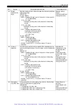
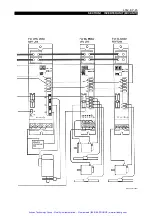
(4) Connection with ICB3H
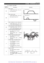
Monitor
terminal
Description
Waveform
M1
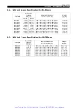
Motor speed
•
Output voltage range: -3 V to +3 V
•
Unit: 1562 min
-1
/V
M2
Motor output torque
•
Output voltage range: -3 V to +3 V
•
Unit: Motor peak torque at 3 V
M3
Motor voltage error (d-axis component)
•
Output voltage range: -3 V to +3 V
•
Unit: V (Output multiplication 1/42)
M4
Motor voltage error (q-axis component)
•
Output voltage range: -3 V to +3 V
•
Unit: V (Output multiplication 1/42)
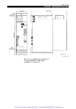
A
A-phase signal of magnetic encoder
•
Vpp in the figure on the right:
2.6 to 4.6 V
(3.3 V when gap is normally
adjusted)
(The signal oscillates around 2.5 V line.)
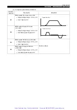
B
B-phase signal of magnetic encoder
•
Vpp in the figure on the right:
2.6 to 4.6 V
(3.3 V when gap is normally
adjusted)
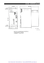
Z
Z-phase signal of magnetic encoder
•
Vz in the figure on the right:
1.4 V or above
•
Vz2 in the figure on the right:
0.5 V or above
•
t1, t2 in the figure on the right:
0.1 to 0.4T
("T" changes according to the rpm.)
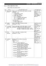
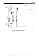
R
Resolver signal
•
Vpp in the figure on the right:
6.0 V (typ)
•
T in the figure on the right:
About 102.4
µ
sec (9.77 KHz)
("T" changes slightly according to
the rpm.)
Speed waveform
Torque waveform
t
t
B-phase signal
Z-phase signal
Vz2
Vpp
Vz1
T
t1
t2
A-phase signal
2.5V
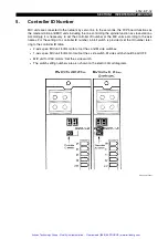
ICB-H
t
Artisan Technology Group - Quality Instrumentation ... Guaranteed | (888) 88-SOURCE | www.artisantg.com


