Field procedure
85
•
Your first measurement in an unknown area has to be large enough to get representative values.
All further control measurements should be adjusted individually.
•
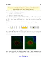
What is the form of the object you search? If you are looking for an angular metal box, the
identified object in your graphic should have a form according to this.
•
To get better values concerning depth measurements, the object has to be in the center of the
graphic, which means it has to be framed by normal reference values (normal ground). If the
object is on the side of the graphic and not totally visible an estimated depth measurement is not
possible and also measurement of size and form are limited. In this case, repeat the scan and
change the position of your scan area, to receive an optimal position of the anomaly inside of the
graphic.
•
There should not be more than one object in a scan. This will influence the depth measurement.
It is useful to scan partial areas over such targets.
•
You should do at least two controlled scans to be more sure about your results. This is also
important to recognize areas of mineralization.
•
Most important rule when dealing with mineralization.
REAL TARGETS DON'T MOVE!
If your
target moves then it is most likely mineralization.
8.3.1 Orientation of probe
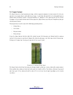
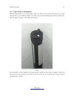
During one measurement the probe should have always the same distance to the ground. Generally we
recommend a height of about 5 – 10 cm from the surface of the ground if possible.
In the event that you are going to go over stones, wood or high grass that is higher, start your scan with
the sensor higher right from the beginning. In circumstances like these, then perhaps you will need to
start the scan with the probe at a height of 2 feet (50 cm) and keep it at that level for the entire scan. It
is important to maintain the height, this will eradicate many errors. As a rule, do not change the height
during a scan for it may create unnecessary errors.
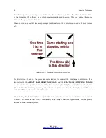
Another important aspect is the physical orientation of the probe. During the “Parallel” scan mode the
orientation of the probe does not change because you are always measuring in the same direction. Even
in the “Zig-Zag” scan mode the orientation of the probe must not be changed. That means you are not
allowed to turn yourself with the device and the probe at the end of the scanning path. Instead you
should walk backwards and continue scanning. Otherwise your obtained graphic includes red or blue
stripes. These stripes throughout a scan are commonly referred to as “Rotational Errors”.
8.3.2 Parallel or Zig-Zag?
For skilled users of the eXp 4500 both scan modes are suitable. According to experience the best
graphics has been received in the “Parallel” mode, because you are starting at the same point and
traveling in the same direction. It is also easier to control your walking speed and direction.
OKM GmbH
www.okmmetaldetectors.com
Содержание eXp 4500
Страница 1: ...FS Future Series eXp 4500NT Version 1 5 User s Manual ...
Страница 5: ...5 9 2 Control Scans 93 OKM GmbH www okmmetaldetectors com ...
Страница 9: ...1 Introduction CHAPTER 1 Introduction ...
Страница 14: ......
Страница 35: ...3 Technical Specifications CHAPTER 3 Technical Specifications ...
Страница 39: ...4 Scope of Delivery CHAPTER 4 Scope of Delivery ...
Страница 44: ......
Страница 78: ......
Страница 88: ......


