background image


2.8


Initialization Functions 


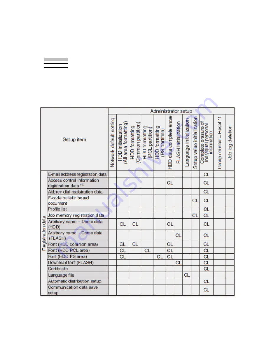
Items that can be initialized by the Administrator 

The following table shows the setup items that can be initialized by administrator. 
 

The gray colored items indicate that the data is stored in the CU side. 

                        The white items indicate that the data is stored in the scanner unit side. 
 
The items with the characters 

“CL”

 indicate that the registered 

data will be deleted


when this function is executed. 


The items with the characters 

“FR” 

indicate that the data will be 

returned to the default 

setting 

when this function is executed. 


46 

Содержание MC-860 / CX2633MFP

Страница 1: ...r assumes no responsibility for the results of errors beyond its control While all reasonable efforts have been made to make this document accurate and helpful as possible we make no warranty of any k...

Страница 2: ...2 7 3 Test Print Monitoring Printer Environmental Conditions 2 7 4 Color Registration Error Correction Test 2 7 5 Density Error Correction Test 2 7 6 Consumable Item Counter Display 2 7 7 Factory Ship...

Страница 3: ...onnectors 1 Turn OFF the power of the MFP Select Setup then Shutdown Follow the on screen prompts When shutdown is complete turn off the power switch on the printer 2 Clean the surface of MFP 3 Note D...

Страница 4: ...Lever Press the top cover button and open the top cover Caution Failure to proceed with caution may result in burn injury The fuser unit gets very hot Do not touch the surface of the fuser unit Top Co...

Страница 5: ...ler in the same procedure for the feed roller only Pad is not used Pull out the tray Clean the feeder roller large and the feeder roller small with a clean cloth wrung out using clean water Feed Rolle...

Страница 6: ...open the top cover Remove the four image drum cartridges from the MFP Drum Cartridges Cover the removed image drum cartridge with a black paper Note Use caution when handling the image drums Be very...

Страница 7: ...Fuser Unit Lock Lever Blue Remove the Transfer Belt unit from the MFP Transfer Belt Retaining Screws Blue Transfer Belt Thoroughly clean the interior of the printer and re install the transfer belt fu...

Страница 8: ...roller with a clean cloth wrung out using clean water or neutral detergent Note Clean the entire surface of the roller by rotating the roller by hand Some types of rollers can rotate in one direction...

Страница 9: ...able cover Platen Glass Scanning Glass Document Retaining Pad Clean the surface of the document retaining pad the platen Glass and the scanning glass with a clean cloth wrung out using clean water or...

Страница 10: ...he MFP enters this condition waiting for password entry 2 When the password that is entered by maintenance service engineer matches the specified password the service menu is displayed Special Operati...

Страница 11: ...ent This is not a covered expense under any machine warranty and you will incur the cost of the replacement components Operation required to exit the Service Mode Screen In order to complete operation...

Страница 12: ...2 2 Service Maintenance Menu Overview System Maintenance Screen Panel Maintenance Screen Copy Maintenance Screen Scan Maintenance Screen Fax Maintenance Screen Printer Maintenance Screen 12...

Страница 13: ...one Country Code When Closed Echo support None TX Modem transmission speed None Echo support None RX Modem transmission speed None Pulse Make Ratio None ON period None MF Tone Duration Off Period None...

Страница 14: ...at HDD is selected the following confirmation screen is displayed When Yes is selected the screen exits the menu and initialization of the HDD starts For details of the HDD initialization refer to Sec...

Страница 15: ...ting factory default value When All Reset is selected the following confirmation screen is displayed When Yes is selected the screen exits the menu and contents of the EEPROM FLASH ROM and HDD are res...

Страница 16: ...placement This is not a covered expense under any machine warranty and you will incur the cost of the replacement components 2 4 Panel Maintenance LED Test All LED lamps are illuminated to check if an...

Страница 17: ...n order to check if there are inactive pixels on the LCD Operating procedure The following three kinds of test patterns can be displayed To select the test patterns press the SETUP key Press the SETUP...

Страница 18: ...he keys Therefore all keys should be pressed in the specified order in order to check that all keys have been pressed Operating procedure When this test is selected the panel key test screen is displa...

Страница 19: ...performed When the scanner lamp is replaced When the mirror carriage adjustment is performed When the scanner Main PCB is replaced Operating procedure When this item is selected Confirm that the RADF...

Страница 20: ...at the scan start position in the vertical scanning direction during FBS scanning stays within the reference value If shade is scanned at the top end of a document make adjustment in the positive dire...

Страница 21: ...n angle Setting for ADF back side Perform adjustment so that the rear end scan position in the vertical scanning direction during ADF rear side scanning stays within the reference value If shade at th...

Страница 22: ...How to release the mirror carriage mode When the MFP remains in the mirror carriage mode the following standby screen is displayed Remove the screws at the locations specified in the illustration and...

Страница 23: ...D signal The MFP responds against the second DIS signal and sends out the DCS signal With this setting the MFP can send out the DCS signal under a good line condition with less echo This setting is us...

Страница 24: ...en it detects the tone signal of 2100 Hz operation of the echo suppressor is stopped temporarily Modem Transmission Speed TX During Transmission 33 6 Kbps 28 8 Kbps 14 4 Kbps 9 6 Kbps 4 8 Kbps Sets th...

Страница 25: ...g value is 0 the MFP runs at the initial value of each country When any value other than 0 is set the Calling Timer can be selected in the range of 1 to 255 mm Attenuator Range 0 dB to 15 dB Sets the...

Страница 26: ...reen of the service menu 2 7 Printer Maintenance Personality Default setting of the PDL language that is supported by the respective destination specification can be changed The PDL language that has...

Страница 27: ...iagnostic mode 2 When the screen enters the self diagnostic mode Level 1 the DIAGNOSTIC MODE is displayed Press either 2 key or 8 key to move to the respective self diagnostic items Menu item scrolls...

Страница 28: ...Level 1 Diagnostic Screens 28...

Страница 29: ...5 DENS ADJ TEST Density error correction system normal or defective Consumable Item Counter Display See section 2 7 6 CONSUMABLE STATUS Consumable items consumption status display Consumable Item Acc...

Страница 30: ...30...

Страница 31: ...nput sensors and switches of the print engine 1 Enter the self diagnostic mode Level 1 and press the 2 key or 8 key until SWITCH SCAN is displayed in the top of the screen Press the 6 key to execute T...

Страница 32: ...nsor H Up L Down RFID COLOR 1 RFID antenna K UID H RFID antenna Y UID H RFID antenna M UID H RFID antenna C UID H F RL FI BL DT DC Fuser release sensor H ON L OFF Fuse entrance sensor H ON L OFF T1 PE...

Страница 33: ...sponding unit runs for 10 seconds Note After running for 10 seconds screen returns to the item 2 state When the corresponding switch is pressed the test program restarts The clutch solenoid repeats ON...

Страница 34: ...MOTOR FUSER MTR REV FUSER_RLS REGIST MOTOR T1 HOPPING MOTOR FRONT MOTOR REGIST SHUTTER EXIT SOLENOID DUPLEX MOTOR DUPLEX CLUTCH T2 HOPPING MOTOR If option installed T2 FEED CLUTCH If option installed...

Страница 35: ...per column and the setting value is displayed in the lower column of the display window The setting value that is displayed last is applied Pressing the 4 key determines the setting value and the scre...

Страница 36: ...nt data Pattern 7 that is contained in the local print function is used for test print with 100 setting of each color it causes offset To prevent offset select the print setting of each color so that...

Страница 37: ...urement value unit L Lower thermistor measurement value unit C Lower thermistor AD value unit HEX Pressing the 2 key switches the display When the key is pressed the screen exits the test Screen retur...

Страница 38: ...etting value unit HEX FRM Frame thermistor read out AD value unit HEX xxx Frame temperature unit C Pressing the 2 key switches the display When the key is pressed the screen exits the test Screen retu...

Страница 39: ...e upper column of the display window and RESULT is displayed in the lower column of the display window When the 2 key is pressed test results are incremented and displayed in order When the 8 key is p...

Страница 40: ...or registration error correction belt reflectance Good Bad Judgment BLT REFLECT RSLT Referring to the result of color registration error correction belt reflectance Good Bad judgment 2 7 5 Density Err...

Страница 41: ...T is executed The message is displayed but does not function AUTO CALIBRATION is executed Automatic setting of the density sensor sensitivity correction value is executed The ON LINE lamp blinks When...

Страница 42: ...isplayed after the data is converted to the equivalent value of A4 3Page Job FUSER UNIT Prints Number of sheets up to the present time since the new FUSER unit has been installed TR BELT UNIT Images N...

Страница 43: ...rinted sheets for each color are displayed TOTAL SHEET CNT Prints Total number of printed sheets are displayed 2 7 7 Factory Shipping Mode Switching This self diagnostic menu is used to switch the PU...

Страница 44: ...s sensors This menu enables service engineer to Disable or Enable the error detection temporarily When use of this menu is completed be sure to return the setting values to the default 1 Enter the sel...

Страница 45: ...of the ID installation check job ENABLE To detect UP DOWN SENSOR DISABLE Not to detect Sets Enable Disable of the ID UP DOWN sensor operation ENABLE To stop REG ADJUST ERROR DISABLE Not to stop Sets...

Страница 46: ...red items indicate that the data is stored in the CU side The white items indicate that the data is stored in the scanner unit side The items with the characters CL indicate that the registered data w...

Страница 47: ...Initialization Functions Admin Page 2 47...

Страница 48: ...1 The group counter Reset is confidential and menu is not open in FCS 4 When HDD Disable is set only administrator can log on Because the access control mode setup values is stored in Flash but the us...

Страница 49: ...tions regarding description in the table are added The gray colored items indicate that the data is stored in the CU side The white items indicate that the data is stored in the scanner unit side The...

Страница 50: ...Initialization Functions Service Engineer Page 2 50...

Страница 51: ...Initialization Functions Service Engineer Page 3 51...

Страница 52: ...are initialized 4 When HDD Disable is set only administrator can log on Because the access control mode setup values is stored in Flash but the user information is not stored in HDD 5 When destinatio...

Страница 53: ...it is repeating or random Continuous defects in the process direction such as voids and lines are the most difficult to diagnose Inspect the visible surfaces of all rollers for obvious defects If no d...

Страница 54: ...ing is complete Leaving the printer in Factory Mode may cause erratic operation of the MFP 3 3 Things to observe when analyzing Test Pages Streaks in Process Direction in the direction of feed paralle...

Страница 55: ...ter that Apply Imaging Unit LED Head Transfer Unit HVPS PU Board Troubleshooting Steps Resolution 1 Verify all packaging material has been removed form the toner cartridges Yes Go to Step 2 No Remove...

Страница 56: ...rint the 100 Solid Fill test print Can the problem be isolated to one primary color Yes Go to Step 3 3 Remove the Toner Cartridge and check for toner starvation in the Imaging Unit Is there evidence o...

Страница 57: ...rinter settings 2 Remove the Toner Cartridge and check for toner starvation inside the Imaging Unit Is there evidence of toner starvation Yes Replace the Toner Cartridge No Go to Step 3 3 Are the LED...

Страница 58: ...y Imaging Unit LED Head HVPS PU Board Troubleshooting Steps Resolution 1 Ensure the media is approved and the Control Panel and driver settings match the loaded media Try different media to verify con...

Страница 59: ...replace the Imaging Unit No Go to Step 3 3 Print the 100 Solid Fill Test pattern and check for any missing colors Is the problem with a single color Yes Go to Step 4 No Go to Step 6 4 Is there debris...

Страница 60: ...t ID Check Pattern and Demo page Reports Information Demo Page to see if it is an application problem Perform isolation Test Prints form Section 2 7 3 Run the Density Error Correction Test in Section...

Страница 61: ...tioning correctly Yes Go to Step 4 No Replace the solenoid or harness 4 Inspect the Transfer Unit for tears or damage on the edges of the belt Is the belt damaged Yes Replace Transfer Unit No Go to St...

Страница 62: ...he LED Head of the problem color with any other LED Head Print a Supplies page Has the problem moved with the LED Head Yes Replace the defective LED Head No Go to Step14 14 Replace the Registration Se...

Страница 63: ...4 1 Troubleshooting Paper Feed 4 1 1 Paper Feed Sensor Details Diagram showing paper detection sensors in the print engine 63...

Страница 64: ...x entry EXIT DUP IN DUP R 385 Around Fuser Unit Fuser thermister 390 Feed error at front feeder IN2 WR 391 Tray1 IN1 392 Tray2 2nd IN 400 Paper size error IN1 Diagram showing paper detection sensors i...

Страница 65: ...ion paper sensor 4 1 2 Jam Removal Procedure Front Cover Block Code 372 380 390 391 400 Open the front cover If either top end or rear of a jammed paper is visible draw out the jammed paper gently wit...

Страница 66: ...er lever shown in blue in the direction shown by the arrow 3 Hold the handle and remove the fuser unit and place it on a flat workbench 4 Raise the jam release levers at two locations and draw out the...

Страница 67: ...cartridges and place them on a flat workbench 2 Cover the removed image drum cartridge with a black paper 3 Draw out the jammed paper gently with care 3 2 1 5 4 4 Return the image drum cartridges back...

Страница 68: ...Note Before removing the duplex unit be sure to turn OFF the power of the MFP 1 Remove the Duplex Unit 2 Press the jam release lever of the duplex unit to open the duplex unit cover 3 Draw out the jam...

Страница 69: ...he jammed paper is removed open the MP tray push up the center lever Then the front cover can be opened or closed RADF Unit Note If the jammed paper cannot be removed easily do not remove with excessi...

Страница 70: ...o step 4 Note Do not pull the document out with excessive force 3 When the jammed paper is removed go to step 9 4 Open the inside cover 5 If top end of the jammed paper is visible pull it out gently I...

Страница 71: ...jammed paper is removed close the inside cover and go to step 9 7 Rotate the dial so that the jammed document is unloaded 8 Raise the document tray Remove the jammed document gently 9 Close the docume...

Страница 72: ...CPU cooling fan error on CU PCB Is the CU fan connector connected normally Does the MFP recover from the error when the fan is replaced Re connect fan Replace fan Replace TBM PCB 054 Communication er...

Страница 73: ...voltage power supply I F error Is the cable between PU PCB and High voltage power supply connected normally Is there defective contact Check for defective contact in the high voltage system Replace th...

Страница 74: ...toner lock lever set Rotate the toner lock lever that fixes the toner cartridge to the locking position Turn OFF the power and back ON Replace the toner sensor Assy 167 169 Thermistor Slope Error Com...

Страница 75: ...y Turn OFF the power and back ON Replace the Belt thermistor 918 Duplex FAN Alarm Duplex internal FAN error Check that the Duplex unit is installed properly Check that the FAN is connected properly Re...

Отзывы: