


Unsupported Duplex Unit Rom
1.
Reseat the Duplex Unit
2.
Cycle the printer's power.
3.
If the problem persists follow the procedure below.
1.
Duplex Unit
2.
Engine Control Board
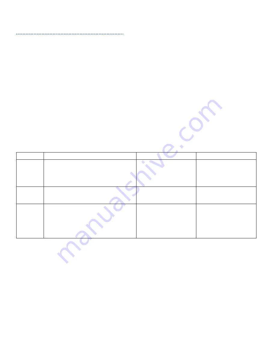
Steps
Action Taken
Yes
No
1
Check the following for evidence of
fault or damage:
Duplex Connector
Is there any damage?
Replace any damaged
parts.
Go to Step 2.
2
Check that the Duplex Unit is
correctly installed and fully seated.
Go to Step 3.
Reseat the Duplex
Unit
3
Check the Duplex Unit version using
the Printer Configuration Sheet
Is the version current?
Replace Engine
Control Board
if the error persists,
replace the DUPLEX
harness.
Replace the
Duplex Unit.
Error Codes that Apply
Initial Troubleshooting Actions to Take
Parts of the Printer that Apply
Troubleshooting Procedure
360