


© 2015 OJ Electronics A/S
14
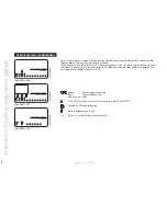
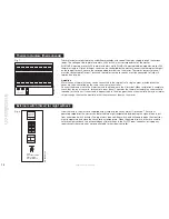
setting the channel
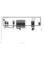
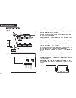
Each room sensor can be set to operate a specific output which in turn controls a thermal actuator
on the manifold. A selector can be accessed under the front cover of the unit where the number of its
output (i.e. its channel number) can be set with a screwdriver (see fig. 10). Up to 14 channels can be
set on the selector, and there are two auxiliary channels (see later). A WLM3 master has 8 outputs. It
can be connected with an add-on slave module with an additional 6 outputs, creating a system with 14
individual zones.
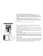
Please note that channels 10 to 14 are marked as A through E on the selector,
A room sensor set for channel 1 will activate the thermal actuator connected to output 1 on the master.
The channel number can be set before power is connected to the system. The channel set on the room
sensor can be changed afterwards if needed.
If two room sensors are placed in the same room and set to the same channel, temperature will be
controlled by the average of the temperature recorded by both units.
Channel 0:
Each Room sensor is delivered with the switch in position 0. It must therefore be set to operate correct
channel output. Channel 0 can also be used for a room controller which is only used to control a group
(area) of room sensors without actually controlling the room in which it is installed (e.g. a controller in
the kitchen which is only used to control sensors located in other rooms). Setting the room controller
to channel 0 means that times and temperatures must be set on the WLCT3 for the group (area). The
WLCT3 will not, however, control a specific output itself.
Channels 1..14:
A room sensor set for Ch1 will activate the thermal actuator connected to output 1 on the master. If
several room sensors are set to the same channel number, heating will be controlled in the following
way:
- Actual room temperature will be calculated as an average.
- The room temperature setpoint will be calculated as an average.
- If floor sensors are connected to the room sensors:
The lowest value of any floor sensor is used as the minimum limit temperature.
The highest value of any floor sensor is used as the maximum limit temperature.
Channel 15
(position F on the switch): Party and holiday function.
Special function. “Special Features” for further instructions.
testing the system:
See “Guidelines and Special Features – Power-up recommendations”.
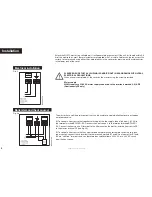
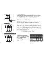
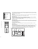
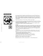
installation
Fig. 10
BR1026A07
a
© 2015 OJ Electronic
A/
S
Jumper
-G
B
BR1026A07a
Содержание WLCT3
Страница 55: ...2015 OJ Electronics A S 55...


