© 2015 OJ Electronics A/S
51
introduction
Product programme
WLTA3-19/29 Room sensor with temperature adjustment
WLTM3-19/29 Room sensor with temperature adjustment and mode switch (Auto, Day, Night, OFF)
WLTD3-19/29 Room sensor with temperature adjustment, mode switch (Auto, Day, Night, OFF) and
floor limit sensor
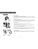
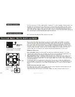
Mounting of room sensor (fig. 2)
The room sensor is used for comfort temperature control in rooms. The unit should be mounted on
an internal wall approx. 1.4-1.7 metres above the floor in such a way as to allow free air circulation
around it. Draughts and direct sunlight or other heat sources must be avoided.
Wired room sensors
Only OJ units which are suitable for two-wire communication can be used.
Standard installation cable of minimum 2 x 0.25 mm² can be used. Units can be connected in
conventional star formation or in bus mode (daisy chain).
The master has four sets of terminals marked SENSOR/CONTROLLER BUS that can be used for
connecting the 2-wire signal cable from the unit.
There are 4 identical sets of terminals for convenient installation. Any unit can be connected to any
pair of terminals. The total length of the 2-wire system can be up to 300 m with a maximum length
of 100 m between any two units. Remember to c to + and – to – .
Wireless room sensors
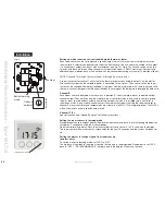
Remove the plastic battery pull tab. The plastic battery pull tab may not be removed before the
master is in learning mode. For further information, see “Installation - Room Sensors - Wireless
Setup”.
Waterline room sensors - type Wltx3
Room sensors
connected in
daisy chain
Room sensors
connected in star
formation
Fig. 1:
Removing the front cover
Fig. 2
BR1026A01a
1.4-1.7m
© 2015 OJ Electronic
A/
S
BR1026A01a
BR1026A02a
© 2015 OJ Electronic
A/
S
BR1026A02a
Содержание WLCT3
Страница 55: ...2015 OJ Electronics A S 55...


