background image

4

20039847GB

3. 

Burner Technical Data

3.1. General

burner types: • 1-stage burners


KP-6


KP-6 L


KP-6-2

• 2-stage burners (”H” burners)

 KP-6 

LH

 KP-6 

H-2

on standard version the burner can be hinged to both sides

the burner must be installed in such a position, that the motor shaft lies horizontally; but the
burner must not, however, be installed upside down.

burner control unit internally connected

safety switch (limit switch) on hinged flange

control switch

air regulation: • stepless adjustable (1-stage burners)

• servomotor (2-stage burners)

oil pump atomising pressure:• 700 - 1400 kPa (7 - 14 bar) (1-stage burners)

• 700 - 2500 kPa (7 - 25 bar) (2-stage burners)

standard version equipped for two-pipe system

electrical connection with a plug connector (KP-6, KP-6 L, KP-6-2).

Extra equipment

run hour counter

filter Oilon 20

de-aerator Tiger Loop

oil meter

oil pressure gauge and valve

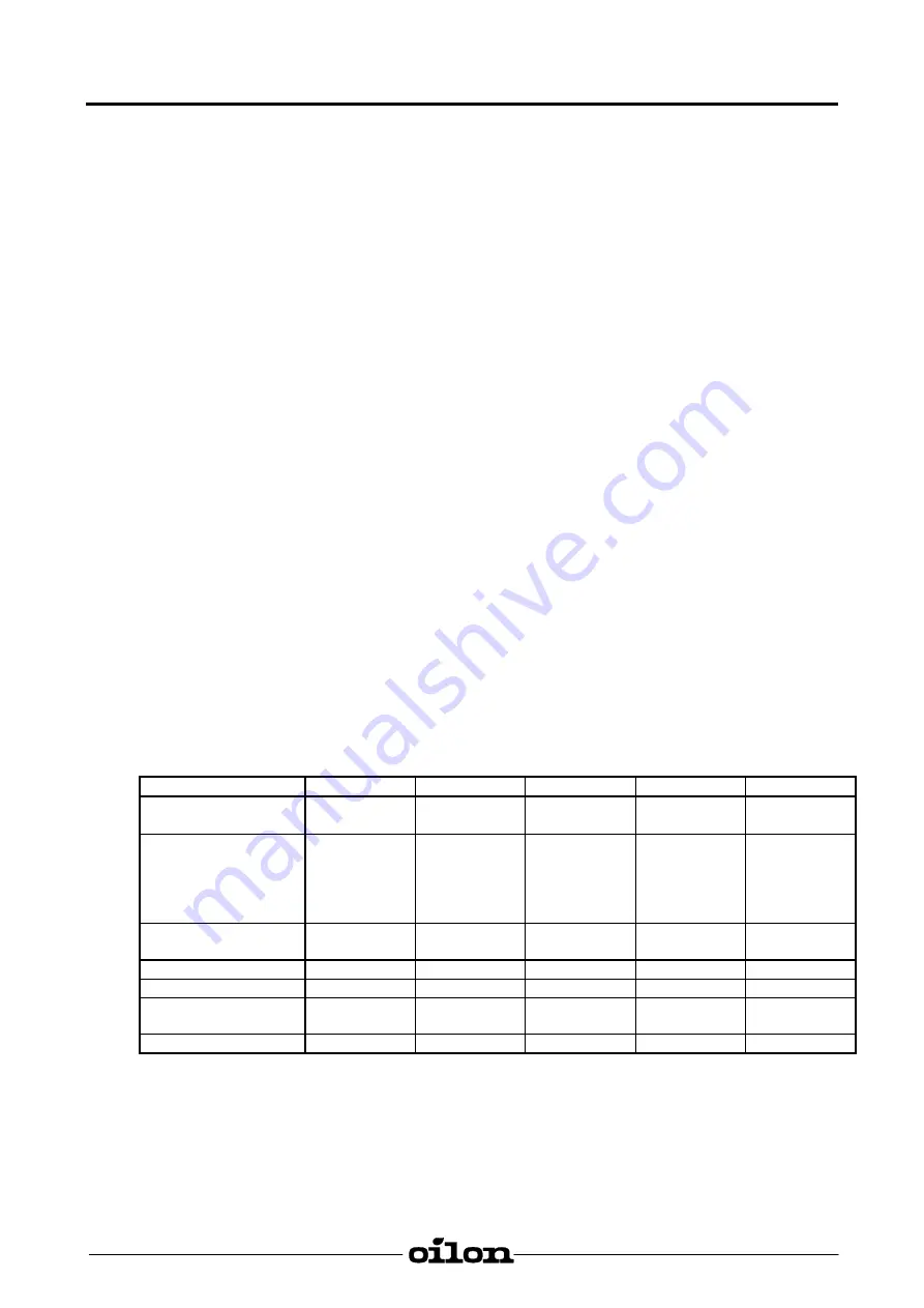
3.2. Technical 

Data

Burner

KP-6

KP-6 L

KP-6 LH

KP-6-2

KP-6 H-2

Capacity kg/h

kW

3,5 - 10,042 -

120

3,5 - 10,0

42 - 120

3,5 - 10,0

42 - 120

6,0 - 12,0

71 - 140

6,0 - 16,0

71 - 190

Burner motor
Voltage 50 Hz  230 V
Output kW
Current A
Speed rpm

0,125

1,0

2750

0,125

1,0

2750

0,125

1,0

2750

0,125

1,0

2750

0,125

1,0

2750

Control unit

LOA24

/BHO64

LOA24

/BHO64

LOA24

/BHO64

LOA24

/BHO64

LOA24

/BHO64

Servo motor

-

-

SQN

-

SQN

Oil hoses

R ¼"

R ¼"

R ¼"

R ¼"

R ¼"

Oil pump

AS 47 C/

BFP 21 L3

AS 47 C/

BFP 21 L3

BFP 52E L3

AT 2 45 C

AS 47 C/

BFP 21 L3

BFP 52E L3

AT 2 45 C

Preheater W

-

30 - 240

30 - 240

-

-

Light fuel oil 1 kg/h 

 11,86 kW

Содержание KP-6

Страница 1: ...OILON OY P O Box 5 FIN 15801 LAHTI FINLAND 358 3 85 761 Fax 358 3 857 6239 E mail info oilon com 20039847GB OPERATING AND MAINTENANCE INSTRUCTIONS LIGHT OIL BURNERS KP 6 KP 6 L KP 6 LH KP 6 2 KP 6 H 2...

Страница 2: ...2 Stage Burner H Burner with Preheater KP 6 LH 15 7 Burner Automation 17 7 1 1 Stage Burners 17 7 2 2 Stage Burners H Burners 19 8 Burner Adjustment 21 8 1 Capacity Regulation 21 8 1 1 Oil Pump Pressu...

Страница 3: ...t very important information WARNING A warning alerts you to possible danger to person if the instructions are not followed CAUTION A caution alerts you to something that has the potential to cause da...

Страница 4: ...high low burners and LH burners are equipped with a preheater 2 stage burners H burners have a maximum control range from 55 to 100 Required combustion air quantity 15 m for each kg of oil to be burn...

Страница 5: ...tore any inflammable material in the boiler room WARNING Keep the boiler door closed while starting the burner and during burner operation Correct installation and adjustment together with regular ser...

Страница 6: ...r 2 stage burners standard version equipped for two pipe system electrical connection with a plug connector KP 6 KP 6 L KP 6 2 Extra equipment run hour counter filter Oilon 20 de aerator Tiger Loop oi...

Страница 7: ...5 20039847GB 3 3 Basic Assembly Drawing...

Страница 8: ...AS 47 C or BFP 21 L3 KP 6 KP 6 L KP 6 2 10 Adjustment ring BFP 52E L3 or AT 2 45 C KP 6 LH KP 6 H 2 11 Nozzle 28 Nozzle conduit 12 Diffuser disc 29 Cover plate 13 Ignition cable 30 Pressure pipe 14 C...

Страница 9: ...the back wall of short furnaces 1 Mounting plate 2 Gasket 3 Thermal insulation BURNER D2 KP 6 6 L 6 LH 95 KP 6 2 6 H 2 105 The mounting plate must have either two or four M10 threaded holes for the m...

Страница 10: ...ing the locking button and pulling out the plug from the socket at the same time 1 Socket fixed on the burner housing 2 Locking button 3 Plug pull out part 4 5 Connecting the Burner to Oil Supply Line...

Страница 11: ...ion line may cause among other things afterspraying of oil into the boiler It is advisable to use ball valves instead of needle valves The tables give the maximum lengths in meters of return and sucti...

Страница 12: ...connection 2 Return line connection 3 Nozzle connection 4 Pressure gauge connection 5 Vacuum meter connection 6 Pressure regulation 7 Air venting plug 8 By pass plug 9 Filter 10 Solenoid valve NO Oil...

Страница 13: ...n 2 Return line connection 3 Nozzle connection 4 Pressure gauge connection 5 Vacuum meter connection 6 Pressure regulation stage 1 P1 7 Pressure regulation stage 2 P2 8 By pass plug 9 Filter 10 Soleno...

Страница 14: ...1 Clean and check the element 3 and the cup 2 Check that they are not damaged Place the gasket 6 on the bolt of the cup and reassemble the element 3 so that the holes at the end of the element are fo...

Страница 15: ...s out in the flame failure position and the burner shuts down and will not start before resetting the control unit The burner makes then one attempt to start see above If the flame is extinguished dur...

Страница 16: ...return 3 Oil suction 4 Oil pump 5 Pressure pipe 6 Burner fan 7 Burner motor 8 Ignition transformer 9 Ignition electrodes 10 Solenoid valve normally closed NC oil pump BFP 21 normally open NO oil pump...

Страница 17: ...iler temperature or pressure exceeds the set value for control device of stage 2 19 the burner operates at stage 1 When the boiler temperature or pressure is below the set value for control device of...

Страница 18: ...stage 1 normally closed NC 8 Solenoid valve stage 2 normally open NO 9 Pressure regulating valve stage 1 P1 10 Pressure regulating valve stage 2 P2 11 Ignition transformer 12 Ignition electrodes 13 Pr...

Страница 19: ...age supply in control unit and contacts of thermostats closed whereupon the control voltage is received to the terminal 1 in control unit A Start on burner with preheating control signal from terminal...

Страница 20: ...on flame relay s contact Opening of contact in thermostat of preheater does not stop the burner during flame burner has started post ignition till operating position of control unit C Control unit bu...

Страница 21: ...E1 Preheater EV1 Solenoid valve stage 1 TSW Thermostat of preheater EV2 Solenoid valve stage 2 M1 Burner motor fan oil pump B1 Flame detector flame signal Adjustable switching points on the cam switc...

Страница 22: ...ve 1 opens oil atomising begins flame has to be ignited during the safety time otherwise the control unit goes to lockout B Flame forms flame relay is energised whereupon terminals 8 and 3 in control...

Страница 23: ...sure factor see table P1 10 bar according to CEN standard P2 pressure to be used Calculation example Nozzle for a boiler of 100 kW with an efficiency of 0 80 and pressure to be used is 9 bar kg h 11 0...

Страница 24: ...es to the nozzle Changing the nozzle pressures by means of the pressure regulating screw regulates the pump s capacities 1 and 2 Capacity 1 must be 55 70 of the calculated capacity Design values for n...

Страница 25: ...ing drawing shows the distance of the nozzle 4 from the diffuser disc 6 Set the ignition electrode spark gap and distance from the diffuser disc 6 and from the nozzle 4 as shown on the drawing 1 Mount...

Страница 26: ...acity the air velocity in the combustion head is too low Hence it follows that the combustion values become worse Check the combustion values by means of flue gas analysis The following drawing shows...

Страница 27: ...tion of the adjustment ring When the right air quantity has been found retighten the locking screw 1 Locking screw for adjustment ring 2 Indicator 3 Air intake 4 Adjustment ring Position of Nut on Adj...

Страница 28: ...e not however so high that the flame does not react when changing over from stage 2 to stage 1 the setting of the disc V is between discs III and I The servomotor is provided with a release lever 5 Wh...

Страница 29: ...eplacement check by turning the fan wheel by hand that it does not touch the cone The fan wheel can be turned after loosening the sight glass 1 Burner housing 2 Air cone 3 Tip of air cone 4 Sight glas...

Страница 30: ...up time of oil preheater up to the readiness signal given by contact OW approx 1 min t1 Pre purge time approx 13 s t3 Pre ignition time approx 13 s t3n Post ignition time approx 15 s t2 Safety time ma...

Страница 31: ...ontrol unit performs the full starting sequence With every lockout control outputs 3 to 8 and terminal 11 are de energised in less than 1 second while terminal 10 for the remote signalling of lockouts...

Страница 32: ...30 20039847GB 9 5 Measurement of Flame Signal WARNING This control unit is a safety unit Do not open it Any unauthorised tampering can result in unforeseen detrimental consequences...

Страница 33: ...es and keep the burner clean Check regularly the combustion values by flue gas analysis for ex always after the refilling of the storage tank or at least once a year An authorised person should inspec...

Страница 34: ...LH burners faulty air damper servomotor H burners incorrect setting on cam disc of the servomotor H burners Faulty motor Find cause and remedy Replace control unit Replace Replace Correct setting Rep...

Страница 35: ...ne 5 After flame establishment lock out Flame forms When burner runs to stage 2 lockout occurs and then re start H burners Incorrect burner adjustment Dirty filters Blocked nozzle Faulty solenoid valv...

Страница 36: ...istance between diffuser disc and nozzle incorrect Incorrect combustion air adjustment Boiler room not adequately ventilated Nozzle incorrect sized or of wrong type Nozzle worn Incorrect position of a...

Страница 37: ...______________________________________ Installed by ___________________________________________________________ ___________________________________________________________ Miscellaneous ______________...

Отзывы: