44
Model 5380 PFPD Operator’s Manual
Rev. 3.1
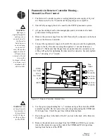
11. Split the air supply using a T-connector and attach one arm of the split supply
to the AUX 4 connector and the other arm to the AUX 5 connector using a
Q
/
i
" nut and ferrule. Make sure that the gas lines are pushed into the connector
as far as they will go before tightening the nuts onto the connectors. Securely
tighten the
Q
/
i
" nuts using a
U
/
qy
" wrench.
12. Remove the preassembled AUX EPC pneumatics kit for the PFPD (Part
#286344) from its container, taking care not to bend any of the previously
formed gas lines.
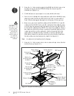
13. Install the AUX EPC pneumatics kit in the open compartment behind the
auxiliary EPC manifold module. Secure its aluminum bracket to the pneumat-
ics compartment using the two supplied Torx T-20 screws (Part #252585).
14. Remove the protective covers from the ends of the preformed gas lines
leading from the AUX EPC pneumatics kit.
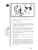
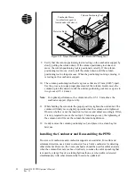
15. Attach these lines to the corresponding gas outlet on the OI gas outlet block
(see Figure 4.10) using a
Q
/
qy
" nut (Part #223057) and ferrule (Part #216358).
Make sure that the number on each gas line and gas outlet to which the gas
line is attached correspond. Make sure that the gas lines are pushed into the
connector as far as they will go before tightening the nuts into the gas outlet
block. Securely tighten the nuts using a
T
/
qy
" wrench.
16. Cut the nylon tyraps holding the
Q
/
qy
" stainless steel gas lines from the PFPD
together. Do not remove the nylon tags designating the COMB and WALL
gas lines. Unroll the gas lines without kinking them.
17. Route the gas lines to the pneumatics compartment in the back of the GC.
18. Remove the plastic protector caps on the ends of the COMB and WALL gas
lines leading from the base of the PFPD, and the protector plugs from the
COMB and WALL gas connectors in the compartment behind the Agilent
6890 GC’s gas control module.
19. Connect the COMB gas line from the base of the PFPD assembly to the open
port below the fine adjust needle marked COMB and the WALL gas line to
the open port on the T-connector marked WALL using a
Q
/
qy
" nut and ferrule
in both cases (Figure 4.10). Make sure that the gas lines are pushed into the
connector as far as they will go before tightening the nuts onto the connector.
Securely tighten the nut using a
T
/
qy
" wrench.
20. Gently turn the fine adjust needle valve (Part #282491) protruding from the
top of the GC’s gas control module to the OFF position (clockwise) (see
Figure 4.10). Do not tighten down as this can damage the needle. Then open
two full turns counterclockwise.
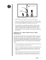
21. Replace the flame arrestor located on top of the detector cap with the barbed
fitting (Part #202077) included in the PFPD Start-up Kit. Attach a gas flow-
meter to the barbed end of the fitting.
!
CAUTION: Do
not use the
needle valve as
an On/Off valve.
Overtightening
can distort the
needle valve’s
seal and make it
unreliable.
Содержание 5380
Страница 89: ...84 Model 5380 PFPD Operator s Manual Rev 3 1 Notes...
Страница 95: ...90 Model 5380 PFPD Operator s Manual Rev 3 1 Notes...
Страница 99: ...94 Model 5380 PFPD Operator s Manual Rev 3 1 Notes...
Страница 107: ...102 Model 5380 PFPD Operator s Manual Rev 3 1 Notes...
Страница 117: ...112 Model 5380 PFPD Operator s Manual Rev 3 1 Notes...
Страница 125: ...120 Model 5380 PFPD Operator s Manual Rev 3 1 Notes...
Страница 133: ...P O Box 9010 College Station TX 77842 9010 Tel 979 690 1711 FAX 979 690 0440 www oico com...


