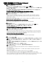
11
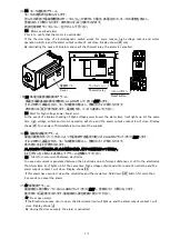
③端子台
1
のR、S、T及びアース端子に配線してください。
警報出力
1
、警報出力
2
、外部操作入力を使用する際には、端子台
2
に配線してください。
端子ねじサイズは
M4
です。
外部操作入力を有効にする場合は、運転条件設定の外部操作設定
F4(P14
参照
)
を実施してください。
外部操作設定時は、外部操作入力に
DC24V
信号を
ON
している間運転をします。
注意外部操作入力の極性を間違えますと外部操作ができません。
Connect the respective wires to R, S, T and ground terminals.
In case Alarm output 1, Alarm output 2 and/or External operation input are used, make connection to the
terminal board 2. Terminal screw size is M4.
To enable external operation input, operating condition setting by F4
“
External operation setting
”
in page
14 is required..
When external operation is set, MISTCATCH operates while 24VDC signal is supplied to the external operation
Input terminals.
Caution If polarity for external operation input is wrong, external operation is disabled.
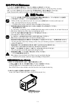
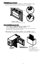
④電源コード引き込み用キャプコンの締付キャップを締めて電線を固定してください。
Tighten the dome nut of the cable gland to fix the cable.
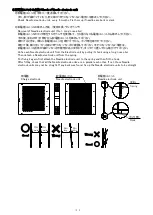
⑤
OMC-E345
配線の際、電線を下図の様に結束バンドで固定してください。
For wiring of OMC-E345, secure the cable using a cable tie as illustrated below.
端子台周辺にファンモータがあるため、電線がファンモータの羽根に巻き込まれないよう注意してください。
The fan motor is located near the terminal board.
Pay attention not to route wires so they can get caught in the fan motor.
⑥電装カバーを取付けてください。
Fit the cover on.
端子台
1
Terminal board 1
端子台
2
Terminal board 2
外部操作入力
External operation input
警報出力
1
Alarm
output1
警報出力
2
Alarm
output2
電源入力(三相
AC200V
)
Power supply (3-phase 200VAC)
R
S
T
DC24V
0V
警報出力
1
、警報出力
2
:
AC250V 2A
、
DC30V 2A
外部操作入力:定格電圧
DC24V
(最大
DC30V
)
入力電流
3.3mA
(
DC24V
)
Alarm output 1, Alarm output 2: 250VAC 2A
、
30V DC
2A
External operation input: Rated voltage 24VDC (max. 30VDC)
Input current 3.3mA(24VDC)
電源コード
Power cable
結束バンド
Cable tie


