


CHAPTER 3 MAINTENANCE PROCEDURES
Navigator Series Service Manual
15
Ohaus Corporation www.ohaus.com
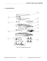
NV models NVT models NVT Approve models
Figure 3-3
Load cell connections, J3
2. NV models require a load cell spacer to be positioned between the load cell and the Base.
Position the load cell back into the lower housing. Turn the scale over to install the (2) load cell
screws. Loosely tighten the screws so that the load cell can be aligned in the housing. While holding
the load cell, fully tighten the screws. The screws should be tight enough so that the load cell does
not move when pushed from the side. Verify that the load cell is centrally located between the ribs.
3. Turn the scale over onto its feet. Position the PCB on to its locating pins. Coil the excess load
cell cable in front of the load cell.
4. Slide the AC jack into its position in the lower housing. Route the AC adapter cable as shown in
Figure 3-4.
NV models
Route wires
Position jack
Position PCB on
locating Pins
Содержание Navigator Series
Страница 1: ...SERVICE MANUAL NavigatorTM Series Scales...
Страница 2: ......
Страница 50: ......
Страница 51: ......


