APPENDIX B - EXPLORER PRO EP LOADER
B-3
B.4 Setup the Balance in Manufacturing Mode
1. Remove power from the balance.
2. Remove the pan.
a. It may be necessary to remove two screws holding the display assembly in place
under the balance.
3. Unclip the display module and ease it forward until the module is clear of the edge of the
draft shield or the edge of the top balance cover on 0.01g and 0.1g resolution balances.
a. Remove the Explorer Pro display module and install an Explorer display.
b. Ensure that the display PCB cannot short to the balance casing.
4. Remove the 2 screws securing the draft shield or top balance cover in place.
5. Remove the plastic pan support clips, if fitted.
6. Remove the draft shield or top balance cover.
7. Install the manufacturing link in the position shown in Figure B-1.
a. Install the link by pushing down on the top and then rotating it 90° to lock it in
position.
b. If a manufacturing link is not available remove the RF shield and locate the hole
through the printed circuit board that was under the manufacturing link access hole.
Short the two pads just to the front of this hole.
8. Apply power to the balance.
9. The balance will come on by itself and display MFG before the normal turn on cycle.
Figure B-1. RF Shield.
Содержание EXPLORER
Страница 2: ......
Страница 4: ......
Страница 62: ...4 10 CHAPTER 4 TESTING ...
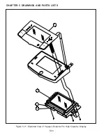
Страница 80: ...5 18 CHAPTER 5 DRAWINGS AND PARTS LISTS Figure5 8 ExplodedViewofExplorerDisplay 1 2 3 O T O T 4 ...
Страница 88: ...5 26 CHAPTER 5 DRAWINGS AND PARTS LISTS ...
Страница 106: ...APPENDIX B EXPLORER PRO EP LOADER B 10 ...
Страница 112: ...APPENDIX D REPLACING BOTTOM DISPLAY BOARD D 4 ...
Страница 113: ......
Страница 114: ...PN 80250985 SERVICE MANUAL EXPLORER EXPLORER PRO AND VOYAGER BALANCES 80250985 ...


