APPENDIX B - EXPLORER PRO EP LOADER
B-4
B.5 Connect the Balance to a PC
1. Connect the RS232 interface cable between the balance and the PC.
a. Note that for a 9-pin to 9-pin cable; ensure the connector marked BAL is connected
to the balance.
2. Check communication between the balance and the PC.
a. In the EP Loader, single-click on the Comm Setup button. The following pop-up
screen will be displayed:
b. Modify the communication parameters of the EP Loader to match the balance, then
single click the Comm Test button. A pop-up screen will be displayed to indicate that
the communication has failed or passed.
B.6 Temperature Compensation (TC) Data Entry
1. Locate the TC Data Label on the balance. It will be under the display module. Refer to
Figure B-2.
Figure B-2. TC Data.
2. Identify the values labeled in the diagram as “A” to “J”, if the balance does not have
internal calibration only “A” to “G” will be on the label. Then input into the TC Data
location of the EP Loader accordingly. The Loader will look like the picture on the next
page.
Содержание EXPLORER
Страница 2: ......
Страница 4: ......
Страница 62: ...4 10 CHAPTER 4 TESTING ...
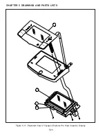
Страница 80: ...5 18 CHAPTER 5 DRAWINGS AND PARTS LISTS Figure5 8 ExplodedViewofExplorerDisplay 1 2 3 O T O T 4 ...
Страница 88: ...5 26 CHAPTER 5 DRAWINGS AND PARTS LISTS ...
Страница 106: ...APPENDIX B EXPLORER PRO EP LOADER B 10 ...
Страница 112: ...APPENDIX D REPLACING BOTTOM DISPLAY BOARD D 4 ...
Страница 113: ......
Страница 114: ...PN 80250985 SERVICE MANUAL EXPLORER EXPLORER PRO AND VOYAGER BALANCES 80250985 ...


