background image


- 5 - 

numberings in RM indicates the number of stored data in current mode (cond/TDS). 


For example, if 20 groups of data is stored in conductivity mode, and 10 groups in TDS 


mode, then the numberings for M+ will be “

M+30

” in both conductivity and TDS mode; 


the numberings for RM in conductivity mode would be “

RM20

”, in TDS mode “

RM10

”.


3.6 

Max/Min Function


Use  this  function  to  display  the  maximum  or  minimum  records  out  of  groups  of  measuring  data.  In 
measurement  mode,  press          ,  LCD  will  display  flashing  icons  of  “

MAX/MIN

”,  indicating  the  meter  has 

entered  the  mode  of  recording  maximum  and  minimum  data.  After  testing,  press          again,  LCD  will 
alternately display the maximum and minimum value in the past measurements. Press            to go back to 
regular measurement mode.   


Conductivity Measurement


4.1 

Preparation


4.1.1  Install the electrode holder 

The electrode holder is comosed of a metal stand base, a supporting pole, and a electrode clip. First, 
install the metal stand base to the meter (screw it on). Please note that the metal base can be installed 
on either side of the meter. Then install the supporting pole on the metal stand base, and then install the 
electrode clip on the supporting pole.


4.1.2  Connect the power adapter 

Plug the power adapter tightly into the DC9V socket. The power’s voltage should meet the requirements 
listed on the power adapter.


4.2 

Conductivity Electrode Information


4.2.1  Conductivity Electrode 

The  meter  comes  with  the  35419-32  combination  conductivity  electrode  (K=1.0)  with  built-in  temperature 
sensor,  which  enables  the  automatic  temperature  compensation.  The  electrode’s  housing  adopts 
polycarbonate materials, which is resistant to shocks and corrosion.


4.2.2  Electrode Connectors 

The  pH  electrode  has  two  connectors:  the  BNC  connector  connects  the  conductivity  sensor;  the  RCA 
connector connects the temperature sensor. Plug these two connectors into  ‘COND” and “TEMP” sockets. 
Please note do not pull the cables in case of poor contact. Please keep the connectors clean and dry. Refer to 
section 6.7 regarding how to properly maintain the pH electrode.


4.2.3  Use the Electrode 

Stir the electrode for a few seconds after it’s dipped into the solution and then let it stand still such that the 
bubbles inside the probe can be removed and a stable measurement can be quickly obtained.


4.3 

Information regarding Calibration


4.3.1  Conductivity standard solutions 

The meter automatically recognizes calibration solutions. 1 point or multi-points calibration (up to 4 points) 

can be adopted. The calibration icons stand for 4 different calibration points (

  stands for two standard 

solutions), see Table-2:


Содержание CON550

Страница 1: ...CON550 Benchtop Conductivity Meter Instruction Manual OAKTON INSTRUMENTS www 4oakton com v2 0...

Страница 2: ...e 4 3 5 Data storage recall and deletion 4 3 6 Max Min Function 5 4 Conductivity Measurement 5 4 1 Preparation 5 4 2 Conductivity Electrode Information 5 4 3 Information regarding Calibration 5 4 4 Co...

Страница 3: ...the meter s response time and measuring accuracy with stable reading display mode available The kit comes with a combination conductivity electrode with temperature sensor measuring conductivity and t...

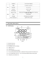
Страница 4: ...dustproof and spillproof Size and Dimension 240 235 103 mm 1kg 3 Instrument Description 3 1 LCD Display 1 Measurement mode 2 Measurement value 3 Calibration icons and numberings 4 Measurement unit 5 T...

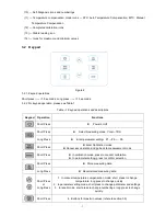
Страница 5: ...suring mode Cond TDS Long Press Enter parameter setting P1 P2 P6 Short Press Enter Calibration mode Cancel any operation and go back to measurement mode Short Press In calibration mode press to conduc...

Страница 6: ...st group of the measuring data Press again to keep storing 3 5 2 Recall stored data In the measurement mode long press key to recall the last stored Measuring data The meter displays RM icon and stora...

Страница 7: ...pter Plug the power adapter tightly into the DC9V socket The power s voltage should meet the requirements listed on the power adapter 4 2 Conductivity Electrode Information 4 2 1 Conductivity Electrod...

Страница 8: ...users can choose the calibration solutions that are close to the test samples to conduct 1 or 2 points calibrations 4 4 Conductivity Calibration take 1413 S as an example 4 4 1 Rinse the electrode in...

Страница 9: ...of the solution 4 6 2 During the process of calibration and measurement the meter has self diagnosis functions indicating the relative information as below Table 8 Table 8 Self diagnosis information o...

Страница 10: ...ting P1 Then press or to change menu from P1 to P2 P7 For details please see Table 10 Table 10 pH Parameter Setting P1 Select electrode s constant 1 0 10 0 0 1 1 Long press to enter P1 2 Press 1 0 fla...

Страница 11: ...lean Before taking a measurement rinse the electrode in pure water It is recommended to rinse it again in the sample solution When submerge the electrode in solution stir the solution briefly to elimi...

Страница 12: ...ENTS any malfunctioned or damaged product attributable to responsibility of OAKTON INSTRUMENTS for a period of three years from the delivery a six month limited warranty applies to probes This warrant...

Отзывы: