


UM10525
All information provided in this document is subject to legal disclaimers.
© NXP B.V. 2012. All rights reserved.
User manual
Rev. 1 — 19 April 2012
6 of 21
NXP Semiconductors
UM10525
120 V 20 W CFL demo board using the UBA2212
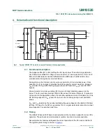
4. Schematic and functional description
4.1 Functional
description
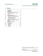
The bridge rectifier (D1 to D4) rectifies the AC input power. The bulk storage capacitor
C
BUF
filters the rectified DC voltage. Power inductor L
FILT
and capacitor C
BUF
form an LC
filter, which attenuates conducted differential mode EMI noise. Fusible resistor R
fuse
provides protection against overcurrent failure.
During start-up, the internal current source connected to HV pin provides power. Once
capacitor C
DVDT
is charged, it provides the dV/dt supply for normal operation. Capacitor
C
FS
provides the high-side floating supply output and Capacitor C
VDD
is used for VDD
bypass.
C5 and inductor L2 primary winding (N1) form an LC tank translating power into the
burner. The L2 secondary windings N2 and N3 preheat the burner filaments. If preheat is
not required in the application, leave off secondary windings and short the filaments. C8 is
DC blocking capacitor. R
CSI
is used for burner current sensing during boost and RMS
states.
R
osc
and C
osc
determine the nominal oscillating frequency based on the Built-in 555-timer
function. The input to the SW pin generates the V
SW
signal which determines the preheat
time. Capacitor C
CB
sets the boost time.
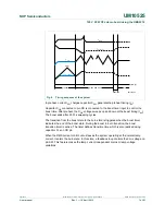
4.2 Timing
The UBA2212 based 20 W demo board provides all the functions needed for correct CFL
operation. These functions include preheat, ignition, boost and on-state operation.
Several protection features safeguard the correct operation of the CFL and controller IC.
The typical system timing is shown in
Figure 4
.
Fig 3.
Typical UBA2212 Circuit for compact fluorescent lamp application
001aan371
Rfuse
D3
CBUF
C5
C8
C7
C6
L2
RCSI
CDVDT
Cosc
CCB
CVDD
Rosc
CSW
CFS
LFILT
D2
D4
D1
U1
OUT
1
14
FS
SGND
2
13
SGND
HV
3
12
SENSE
PGND
4
11
SGND
DVDT
5
10
CSI
V
DD
6
9
CB
RC
7
8
SW
CFL
AC input
L_N
L_L
UBA2212