


UM10525
All information provided in this document is subject to legal disclaimers.
© NXP B.V. 2012. All rights reserved.
User manual
Rev. 1 — 19 April 2012
13 of 21
NXP Semiconductors
UM10525
120 V 20 W CFL demo board using the UBA2212
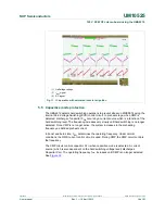
5.4 Saturation
Current
protection
A critical parameter in the design of the lamp inductor is its saturation current. When the
momentary inductor exceeds its saturation current, the inductance drops significantly. This
drop causes the inductor current and the current flowing through the LSPT and HSPT
power switches to increase rapidly. The increase can cause the current to exceed the
half-bridge power transistors maximum ratings.
Saturation of the lamp inductor is likely to occur in cost-effective and miniaturized CFLs.
The UBA2212 family internally monitors the power transistor current. When the current
exceeds the momentary rating of the internal half-bridge power transistors, the conduction
time is reduced. In addition, the frequency increases slowly by discharging C
SW
. This
function causes the system to balance at the edge of the current rating of the power
switches.
Figure 11
shows the Saturation Current Protection (SCP) in real application which uses an
easily saturated inductor. SCP enables the burner to ignite despite the inductor saturating
effect. When the same parameters are used with an IC without SCP, the IC failed during
the ignition.
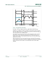
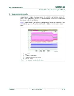
(1) VDD signal.
(2) I
lamp
signal.
(3) Half-bridge voltage.
(4) CB signal timing for boost and transition.
Fig 10. OTP function activated in boost state