


UM10525
All information provided in this document is subject to legal disclaimers.
© NXP B.V. 2012. All rights reserved.
User manual
Rev. 1 — 19 April 2012
14 of 21
NXP Semiconductors
UM10525
120 V 20 W CFL demo board using the UBA2212
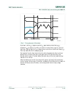
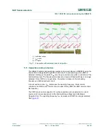
5.5 Capacitive
mode
protection
The UBA2212 detects hard switching operations to prevent stress on MOSFETs using the
internal Zero-Voltage Switching (ZVS) control circuit. In preheat stage, when CMP is
detected, discharge of capacitor C
CB
occurs by a current source which is a function of the
hard switching level. The frequency increases very slowly until hard switching is no longer
detected. Once CMP is no longer active, the system increases to the preheating
frequency as defined preheat current.
In boost and burn state, V
SW
determines the operating frequency. Under normal
conditions, the RMS current control circuit is used. During CMP, the CMP circuit controls
the frequency.
The CMP circuit controls capacitor C
SW
when capacitive mode is detected. A current
source (which is also dependent on the hard switching voltage level) discharges
Capacitor C
SW
. The operating frequency f
osc
, increases until CMP is no longer detected.
See
Figure 12
.
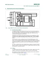
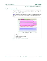
(1) Half-bridge voltage.
(2) I
lamp
signal.
(3) RC signal.
Fig 11. IC operation with saturated inductor at ignition