


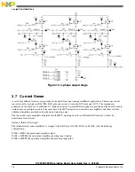


Figure 18. Hall Sensor Interface
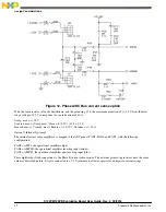
The three signals from the Hall sensor need to be routed to the appropriate timer pins on the microcontroller. For Phase A, a
jumper must be placed on pins 2-3 of header J15. For Phase B, a jumper must be placed on pins 1-2 of header J16. For phase
C, there is a 0-ohm resistor that links it directly to the microcontroller pin PT3.
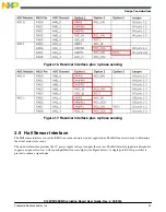
Figure 19. Hall Sensor routing options
Design Considerations
S12ZVM12EVB Evaluation Board User Guide, Rev. 2, 03/2016
24
Freescale Semiconductor, Inc.